-
• #2
Great project!
Tried to glance over the schematics... but missing an easy to access / read .pdf of it. Do not have the infrastructure at hand to read the 'bin' files.
Regarding steering: do you take steering geometrie in respect to curves into account for inner and outer wheel? I'm not seeing it at :25 in the youtube clip and also from what I can see about the mechanical / geometrical layout.
-
• #3
Thanks! I added the schematic and layout pdfs to the repo bolidJs_schematic.pdf and bolidJs_layout_all.pdf .
In the same folder there are gerber files in zip archive which can be viewed even online.About the steering, I made some cutouts to allow for 45deg turns. I was concerned with that for the first version. As it turned out the wheels stick out quite a lot from the chassis plus the suspension was so high the wheel had a small gap under anyway. This time I didnt add little boards that the motor gets glued to and suspension is soldered to. I think I will get away with soldering pogopins directly to the motor terminals. I am still not sure if it will work so I might squeeze those boards in before I send it out for fabricating.
Another thing is that when turning, the wheel that goes forward is way in front outside the board. This is a problem when the car hits something. It can snip the pogopin. I added pads where I want to solder a wire formed to work as a bumper in front. I wanted to have smallest possible pcb so didnt want to make a bumper as a part of the layout. -
• #4
Wow, that's amazing! I can't wait to see it when you get the PCB back from the fabricator!
What are you using an an actuator for the steering? I thought for a white it might be one of those ultra-micro servos, but it looks more like a stepper motor?
Also, is it 4wd, or are you just using the two front motors as bearings?
-
• #5
Thanks Gordon.
I use micro stepper. They are strong enough to move the steering mechanism and are less bulky than servos.
micro_stepper.png
I did consider micro linear servo but the torque isnt that much greater I think and they are more expensive. Those little steppers you can get from china for less than one EUR. Also its fun to control it:) I would put the link to the shop but there is so many of them and links get inactive after a while so its better to google for it.
It is 4 motors but I have a driver per axis so its front and back separate drive. In reality I apply the same power to all. Because there is no gear once you have them going they draw less current so I dont know if you save much power by powering just one axis.
m20_motor.png . I tested out lots of them and they vary a lot. The best one for me was M20. It might depend on the vendor as well possibly? They cost less than one EUR.
Finally this is the pogopin I used. The weight of the car is so little its even too stiff. pogopins.png. I am hoping that this time if I dont use the support boards and solder directly to motor terminals it will add some more suspension action.
I am fabricating 5 boards. I could send out two preassembled with smd components to anyone interested to get involved with it :) I dont have enough mdb42q and motors so you would have to add these by yourself. -
• #6
Thanks! I'd love to be involved but I'm afraid I just don't have the time. This looks so nice though - and I didn't even realise those micro steppers and micro linear steppers were a thing!
Now you've got me thinking about mini robots :)
-
• #7
Its all open so you can build one on your own anyway. I suppose you could put it up in your shop as a kit if it turns out any good.
Yeah, there is so many ideas and so little time :) I am hoping for the bolid to be just a beginning of series of projects.
One of the options I put on the bolid is using supercap instead of 3xAAA batteries. I bought them for some other project that I am working on (which I might post eventually). I hooked it up to the bolid breadboard and it worked great. The cool thing is you can draw a lot of current from them so its nice for the car as it needs initial higher current to get it moving. I bought 15F 5.6V which was reasonably cheap. I think you could get like 20minutes of fun out of it. I measure the voltage drop on it so I can adjust PWM to keep constant torque. Also its super fast to charge.Dont get me started on mini robots :)
-
• #8
I assume the wheel motor drivers are (ti?) DRV8833 Dual H-Bridge Motor Drivers.
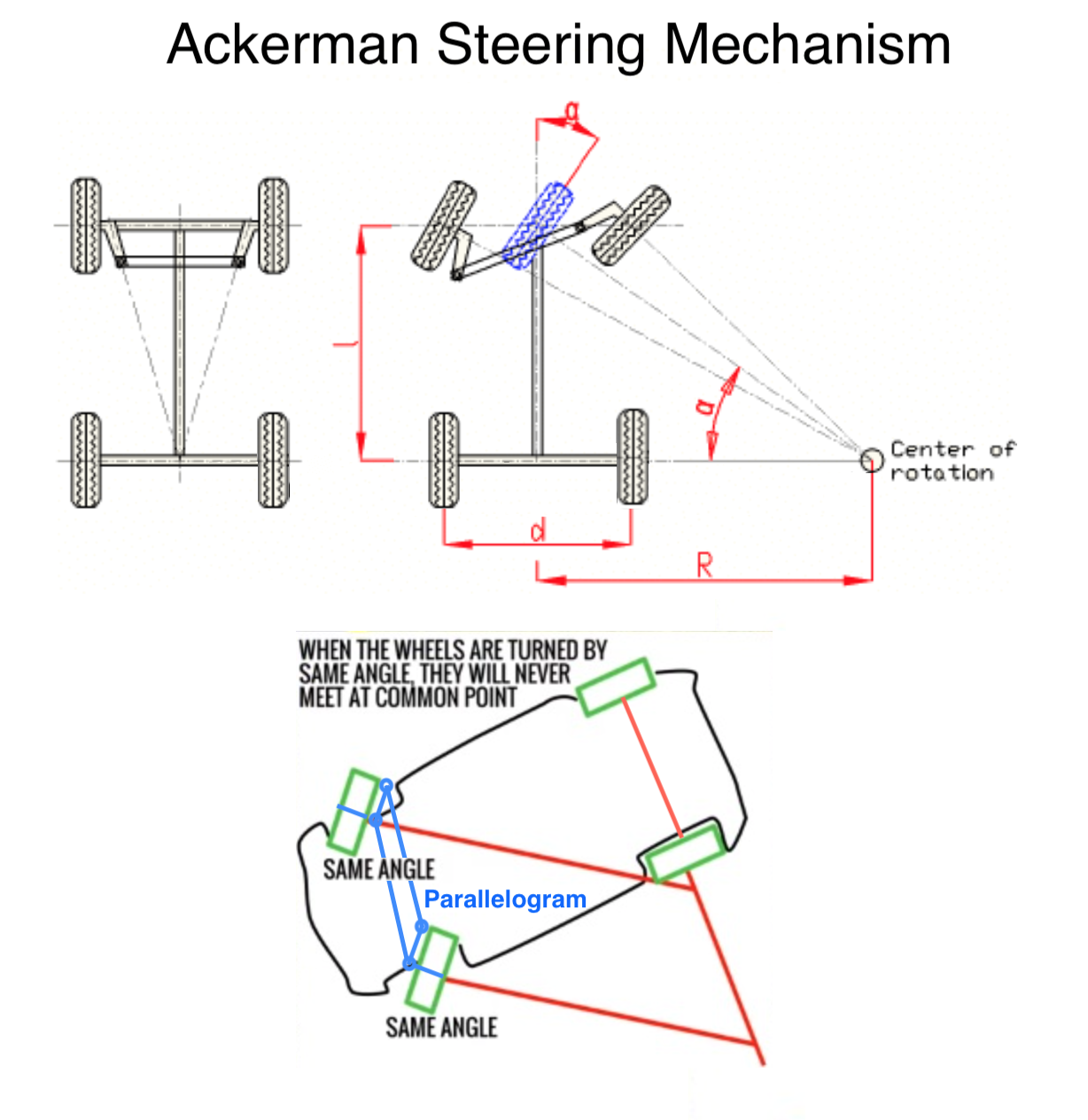
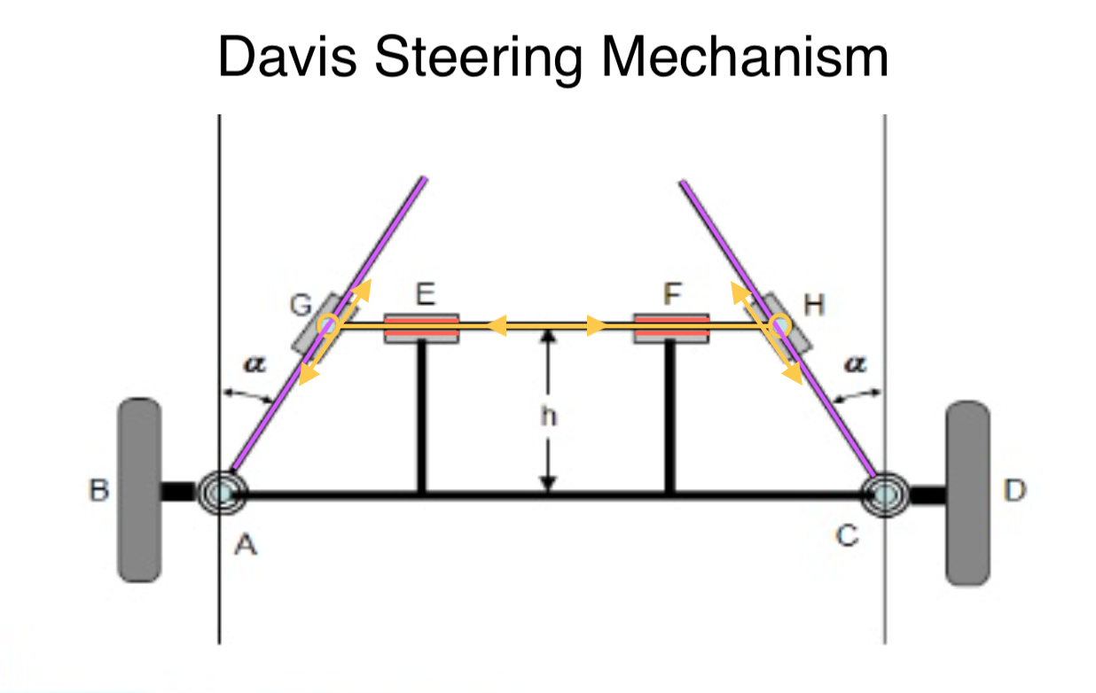
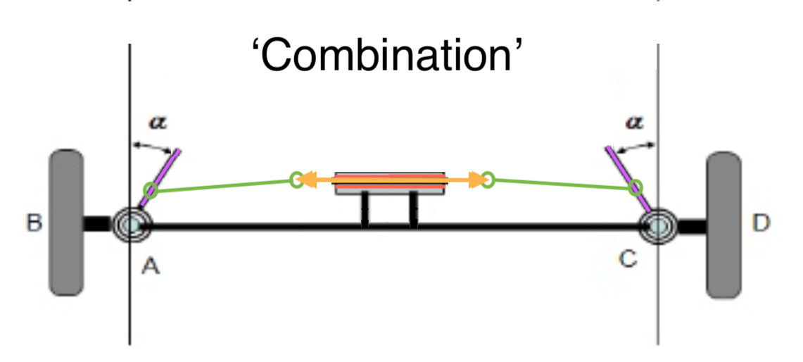
With steering geometry I meant the following the different angles of the front wheels when in a curve... see attached pic... (and, for example, this link: https://gearcraft.blogspot.com/2011/11/steering-car.html). Ackerman (trapez) is geometrically better than just parallelogram. Davis is geometrically perfect but much more complicated to implement and has wear issues compared to the simply to implement Acherman setup (https://www.slideshare.net/jeetamrutiya1/steering-gear-mechanisms-kinematics-of-machines). The wear over time of the slides G, E, F and H demises the accuracy. Some current cars us a combination of slide (rack and pinion 'sliding' in E and F) connected with two link bars to the fixed-length and fix-angled levers (includes space saving), which could work nicely with your setup of the slider on the screw with driven by the micro servo.
3 Attachments
-
• #9
Honestly I wasnt even aware of this. Its great thing to learn about. I guess my implementation is just parallel.
If I get it right it would be enough to just move the rotation points on the T bar toward the middle. The problem with that would be that right now the T bar slides with the plastic screw on the stepper. If T bar gets tilted then it would get stuck?
Thanks for pointing that out. Thats interesting problem. I didnt send out the gerbers for fabrication yet.
As for the drivers I used TI drv8830 drivers for old implementation. This time I will go for LB1930 as they seem cheaper and more widely used for hobby stuff. They are used for one of espruino tutorials I think.
1 Attachment
-
• #10
Thanks for the feedback about the LB1930. I have something in the making with DRV8833 and two similar motors controlled by an MDBT42. I use a 3V cell for the MDBT42 and 4xAAA as power for the motors and auxiliaries. All is held together by some 3D printed pieces.
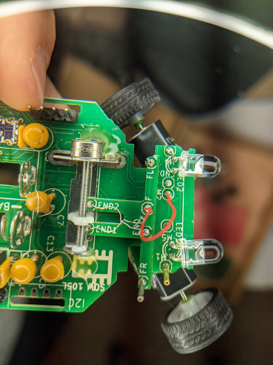
Using the PCB as the car chassis is perfect: fiberglass reinforced resin... (I once used a CD for a RC Car chassis). Very convincing are the pogo-pins for axle/turn, suspension springs and 'ball joints' AND electrical connection. Equally convincing is the setup of end-switches/detectors. Did you ever use them? ...or do you now on init just run the stepper 2 x max steering steps 'ramming' into end pos and then back to center with 1 x max steering steps? Do you have a trim on your controller for setting the center for straight steering?
Moving the vertical turn axis closer to the center plane of the wheel reduces the force on the steering. In cars it is even within the envelope of the tire... last but not least because the wheel-rim construction provides room / space and it is space saving (there is more to steering, but just having a 'perfect' angle for about 2/3rds of the left/right steering extent is usually more than the 80-20 gain-compromise with less than the usual 20 pain...
Btw, great detail picture of the front section with the steering.
Did you 'study' Lean Design / Construction / Engineering? (Could be a good idea to prep some kits and sell... for fun and hassle... :( )
-
• #11
Just looked up the LB1930 and DRV8833 on digikey. Considering drv8833 is two in one it makes very little difference in price. DRV8833 is a better chip with higher output current so maybe its better to stick with it.
I never used the end points in the old version. I just added trimming. It would be nice to have a feedback I guess but was too lazy. The idea was to have the T bar making contact to the pads connected to IOs once the limit is reached. I think there will be debouncing problems. It would be nicer to have some position sensor but it will increase the cost and complexity.
The argument of having lower force for the trapezoid design would be actually important. Those steppers arent too strong.
I would rather have Gordon do the selling in his shop ;) I dont think its good enough to make any significant sale volume.
Saying that, today I bought an RC car for my 2 years old and its absolute rubbish. On/off steering and on/off acceleration. Controlling is terrible. I already think to stick espruino in there and fix it;)
I didnt study lean design. If you point me to some materials I wouldnt mind having a look. -
• #12
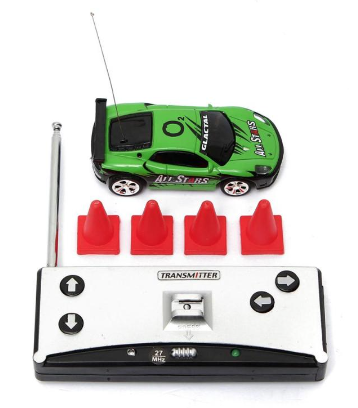
...modified RC car: there are already things on the forum not as elaborate in components... but still good enough to use the electro mechanical part. (on/off drive and direction on single tx/rx chip with 27 or 49 MHz RF signal... yep... technology from 20 years ago... but their front suspension was excellent... micro car - see attached pic
Btw: this is your next challenge (youtube 'DIY 1:150 RC Car ' based on a plastic model, equipped w/ engine, steering, battery, micro and IR controller): https://www.youtube.com/watch?v=bG3rvkpDsdg
Amazing, especially the soldering... just tried that on some equally 'pinned'/padded chip and failed...)ith much less time but more money effort - starting right away this way: buying something like this would be more gratifying, but it is just not the size for a 2-year old (youtube 'Micro scale RC Car gets unboxed and driven!' from Carson Model Sport ): https://www.youtube.com/watch?v=JbooLfzvvAk
Regarding the end switches: bouncing is not an issue, no extra sensor, just what you have going against may be a solid, vertical wire that you solder into the chassis and is touched by the other wire on the T bar. I had made a plotter that has these things and on init / calibration, I drive it into the contact: run fast/multiple steps until getting a contact... then go back until loosing contact and then slowly back into again until contact. There is plenty of time to let the bouncing settle. You though still want to have a trim on the controller.
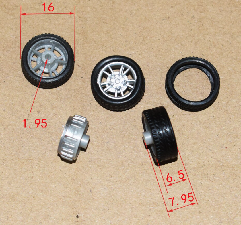
Question: Where did you get the wheels w/ tires that just fit nicely onto the motor axles?
1 Attachment
-
• #13
I have seen the first video, super cool. The guy is really good at micro-mechanics which I am not at all. The second video I havent seen. It looks good. I wonder if they are off the shelf and you can buy it. Maybe I shouldnt bother with my PCB car and just get one of those.
The wheels I get from china, one EUR for 10 wheels :) I dont want to post a link that will get inactive. Just search "mini rubber wheel" on aliexpress. There is lots of shops selling them, I use 16mm. They are not exact fit for the motor axles so I use wire insulation to make tight fit which sucks.
1 Attachment
-
• #14
Maybe I shouldn't bother with my PCB car and just get one of those.
would be a shame... Exactly because people bothered, the maker movement and a lot of new inspired engineers, tinkerers, makers, and foremost fun... came to be. After all, the satisfaction comes much less from owning something than from creating that something - even though much less perfect but with deep, thoughtful (wordplay) and passionate relationship to the thing and its inner workings. It all depends what the use and purpose of the thing is. Whether to buy or DIY follows the same thought process applied in a good business: focus on core business or having a hobby or interest, latters to keep the mind multifaceted. In business, you make the tool to produce the core business product only if it cannot be bought or it is a business strategic asset/differentiator. I can build my own soldering iron,... but why would I? No rule without exception, though.
-
• #15
True, most of the fun is in the making. The thing is that its nice if the project is in some way unique. Anyway, I wouldnt abandon it. Its not much more effort to drive it to the end. Another reason is that I hope people like it enough to build based on the design files or leverage for their own projects.
-
• #16
Hello All! I have the board mostly assembled. I will make an update on that later. Right now I am checking the peripherals and would be nice to have the communication with control device working.
Initially I thought I will use a bluetooth joystick or an app on the android phone making it work as a joystick. Nice option would be to control it from bangle watch. For that my mdb42q board on the rc car would need to be able to take commands from BLE HID device? Is that even possible? I couldnt find any examples or tutorials on doing this direction so I suspect there is a reason for that.
The other option is to write custom app for browser using web bluetooth. Any examples for js web browser joystick would be appreciated as well. Thanks! -
• #17
You could start with the Espruino Flag Raiser app
-
• #18
I guess that would work for communication from espruino device to espruino device. Initially I want to get phone or a joystick as a control device.
-
• #19
great to see bolidJS tagging along. I assume you got your boards. With the hardware done(?), it's software-time!
Not done that much BLE communication (yet), I think there are many good resources to cheat from, last but not least @Gordon 's open source Espruino IDE which can talk to any of the Espruino BLE boards out of the box.
To get started with the Espruino IDE for controlling the bolidJS, take a look at @JumJum 's Testing feature in the Espruino IDE settings, because it is way more than testing: it is Monitoring, Controlling, Logging of connected Espruino devices.
With the Testing/Monitoring feature, you can swap the console against a UI that can have active controls - buttons - that can send any commands to the device through the console connection in the background and retrieve data in custom defined intervals to show in graphs. You can even have a back drop image - imagine - a steering console dashboard for the bolidJS. I have somewhere a modified version of that which goes even further with all kinds of indicator dials, bars, etc.
To checkout some applications of the Testing/Monitoring/Logging feature, take a look at these conversations:
In latter conversation's first post you find an .mp4 clip - f_vs_signal.mp4 - that shows it live.
@JumJum has also produced some youtube videos how to use the Testing/Monitoring/Logging feature.
Happy Soft-Tinkering!
-
• #20
@allObjects Thanks, thats really helpful. I can design simple controller GUI with this. I wasnt aware of that feature of the WebIDE. There is very little info on it. The only info post I found on the forum has a broken youtube link http://forum.espruino.com/conversations/261647/
Fortunately I found some other tutorial videos on youtube. This will keep me going.
Is there any chance to reuse communication mechanisms used in that framework for a standalone web app? I think I will have to write some simple joystick webapp at the end that can be loaded from phone.
BolidJS is functional. I didnt attach the wheels yet so its just hanging for testing. There are two small PCB bugs but I was able to get it working anyway. I will fix it for the release. I am gathering photos from assembly so I can put some step by step instructions and videos. Christmas will be busy :) -
• #21
Too bad I cant just use any Bluetooth HID controller. I saw one post asking about it from few years ago but I think its not possible. It would make things much simpler.
-
• #22
@kri100s, sorry, was not aware that the youtube link is broken. I can give you a quick intro how the testing / monitoring / logging feature works - if you chose to use it to get started. On the other hand, using a second mdb42q seems to me the most useful approach. Connecting a 4-way analog joystick (with or without 'press to enter' feature) is all what it needs.
-
• #23
@allObjects No worries, I will work it out.
Separate joystick is the approach I had for the previous attempt without espruino. If I did it again with espruino board I would keep it as a separate project. I think there might be already project like this by someone else. There are two reasons I wanted to avoid it:- one is that its a separate piece of gear. I wanted to be able to use whatever is around the house and if there are no controllers just use the phone with an android app. As discussed above the HID approach is not an option. Custom phone app using web bluetooth is one that makes most sense to me.
-second is that the last time when I had my own custom built joystick I didnt like the performance. There are knobs modules you can get from china but they have very little angular movement giving signal. You end up with something thats hard to fine control it.
- one is that its a separate piece of gear. I wanted to be able to use whatever is around the house and if there are no controllers just use the phone with an android app. As discussed above the HID approach is not an option. Custom phone app using web bluetooth is one that makes most sense to me.
-
• #24
hard to fine control
Welcome to the input control work... or world. Mice, Trackpoints, Trackpads, Joysticks, you-name-it... came a long way to have that managed.
-
• #25
I don't see a reason why you couldn't interface to a Bluetooth LE device like a joystick - it should pretty much just be a matter of subscribing to notifications on the right characteristic.
The issue I've had has actually been finding something that really is Bluetooth LE - I did order a joystick a while back to try, but it turned out it was legacy bluetooth :(
 allObjects
 kri100s
 Gordon
 AkosLukacs
Hi everyone,
While ago I built an RC car. The requirements were:
That resulted in some design decisions like using 4 small dc motors (no gear) so they can be directly attached to the wheel. Also used pogo-pins soldered to the pcb as suspension and hinges for steering.
Back then I was more bare metal embedded guy so I used some LPC micro with lots of modules for communication and so on.
It worked pretty well. You can see the video here:
rc pcb car
I decided to redesign it with expruino as a control device and add some other improvements. Since the mdb42q module has the regulator already I could drop the dc/dc converter and the wireless communication module. I added third battery in series since I dont have a boost from the DC/DC anymore.
I did some breadboard testing for motors and stepper with espruino and it seems all good. The repo is public and you can find it here: bolidJs repo Right now its just schematic, pcb and some messy test scripts.
I used to have pcb joystick but this time I will just control it from phone or any hid device I think.
I will sent out the board for fabrication this week so any feedback is welcome before it goes :)
I will make some updates once I have the board assembled. This post is for some sense of accomplishment after a week of pcb design and testing espruino with peripherials :)
1 Attachment