-
• #2
Sat 2020.05.02
Well Hello Marek @user112057 and welcome to the Espruino community. Thank you for your interest.
It is likely (hardware) a pull-up/pull-down issue, not enough drive current, both circuits lacking a common ground or (software) the pin mode is incorrect. There isn't enough detail provided for me to make suggestions, but uploading the schematic, lock datasheet, link to tutorial if any and the current attempted code would provide some insight as there are too many combinations to just guess.
Might get some ideas here:
-
• #3
Thank you Robin for your response. Let me elaborate.
I have a 3rd party circuit (an intercom). I can take a wire and short two connectors on this circuit and this triggers the unlocking action. I would like to trigger the same behavior using MDBT42Q. I was hoping I would solder two wires to two GPIO pins on the breakout board of MDBT42Q and connect them to these connectors on the intercom circuit. Than I was hoping I would issue a command and MDBT42Q would open circuit between these PINs therefore shorting the connectors and opening the lock.
Am I explaining this right?
-
• #4
Any luck with the example tutorial in #2 post?
'Am I explaining this right?'
It appears so, but there are a few gotch'as
'take a wire and short two connectors on this circuit'
Are we truly just grounding, pulling a high voltage through it's internal pull-up to ground, or even connecting two high voltages together? What are the voltages? The MDBT42Q is not tollerant.
While there is an internal resistor, it would be safer to verify.
See p.151
http://www.espruino.com/datasheets/nRF52832_PS_v1.0.pdf
20.4.1 GPIO Electrical Specification'using an intercom'
That could be powered by a 9V battery or even 12V or greater. It might be setup with protection circuitry, it might not. I smell smoke if not sure. Do you have resistors in the 5K to 10K to 50K range to use as a jumper to test? If that is successful, then a lesser chance of damaging the GPIO pin when used as an input.
While it is quite possible under the assumption we are just grounding a pin, if one is not ABSOLUTELY sure, I'd play it safe and toggle a 1 cent transitor, which should protect the MDBT42Q and one could then control the resistors/current/grounding of an external circuit. Not enough information for me to make a suggestion.
Review the #2 post example, it seems to be what the project requires.
-
• #5
I low-voltage gate MOSFet will do... see @DrAzzy 's posts. I bought some from his tindie.com selling place a while ago but I could not find the product anymore. See also https://www.espruino.com/mosfets
-
• #6
@Robin thank you so much for your response.
I completely agree that using a transitor would be the right way to go. It's also what @allObjects is suggesting (thanks!). If I understand correctly I would connect G to the ground, S to the connector on intercom I want to ground and D to one of GPIO of MDBT42Q. Than I would control it with a code like
analogWrite(TRANSITOR_D, 1)to close circuit andanalogWrite(TRANSITOR_D, 0)to brake it again. Is my understanding correct?The only problem I have with this approach that I don't have a transitor at hand :) and if I order one online I will have to put my project to a shelf for a week or two until it's delivered.
I measured the voltage between the circuit I need to short using universal meter. They show 0.6V of difference. And it really looks like unlocking is just triggered by grounding this wire. If I understand correctly this means "pull-down" signal, right?
I reviewed the tutorial with the loop and detecting when it gets grounded. I guess it's slightly different than what I need. The tutorial detects that the voltage has dropped. However in my case I need to cause the voltage to drop and the voltage is supplied by the external source (transformer coil of the intercom). Can you please elaborate on how I could cause a voltage drop on a wire connected to GPIO?
Do you have resistors in the 5K to 10K to 50K range to use as a jumper to test?
I don't. But I do have a universal meter. What should I test for?
Btw, you've probably already noticed I have very little knowledge about microelectronics. I write software for living. This is my toy project to learn something outside my field of expertise.
Thank you again for helping me out.
-
• #7
digitalWrite() better choice over analogWrite()
Have to step out for a bit, what time zone are you in so I know if I'll have enough time to answer tonight? Me CST [GMT-5] I'll re-read your last post then.
In the mean time, Check out:
Heading 'Transistor Switch'
halfway down the page:
-
• #8
Thank you Robin.
I'm in CEST (GMT+2) so I'm calling it a night for tonight.
I will continue tomorrow, or more likely on Monday, since it seems I need to find a brick&mortar shop that sells transistors.I really appreciate you help.
-
• #9
Marek, did a bit of digging and came up a few ideas.
The suggested MOSFET wiring in #6 post is not correct. From what you have described, it is most likely the lower set of four, upper left image of the P-Channel design you are after where the intercom is the load.
It could be as simple as setting the pin mode and providing digitalWrite() but after reviewing intercoms with a transformer coil (ref #6 post) implies a higher than required secondary and likely modulated or clipped AC.
Referring again to p.151 of the spec, it will be discovered the GPIO pin cannot survive that voltage nor would it be able to drive enought current.
One of my favorite learning videos is the exploding LED, around 03:08and likely what might happen to the MDBT42Q
Other ideas might be use of a relay or opto-isolator. Tutorials thre also.Without the schematic of the intercom, we are just guessing and that most likely will lead to the unfortunate, unrecoverable 03:08
Any chance you could provide images of the exposed intercom wiring and how the shorting of pins is done?
-
• #10
Hi Robin,
One of my favorite learning videos is the exploding LED, around 03:08
You should check out ElectroBoom youtube channel. It's run by Iranian electric technician living in Canada, who is constantly getting shocked or have stuff catch fire. I find it very entertaining :)
Any chance you could provide images of the exposed intercom wiring and how the shorting of pins is done?
I was trying to make the best photo of the wiring I could get, but really it's quite messy, so not easy to make something out.
So I googled around for this intercom model and actually internet came through:) I'm attaching:
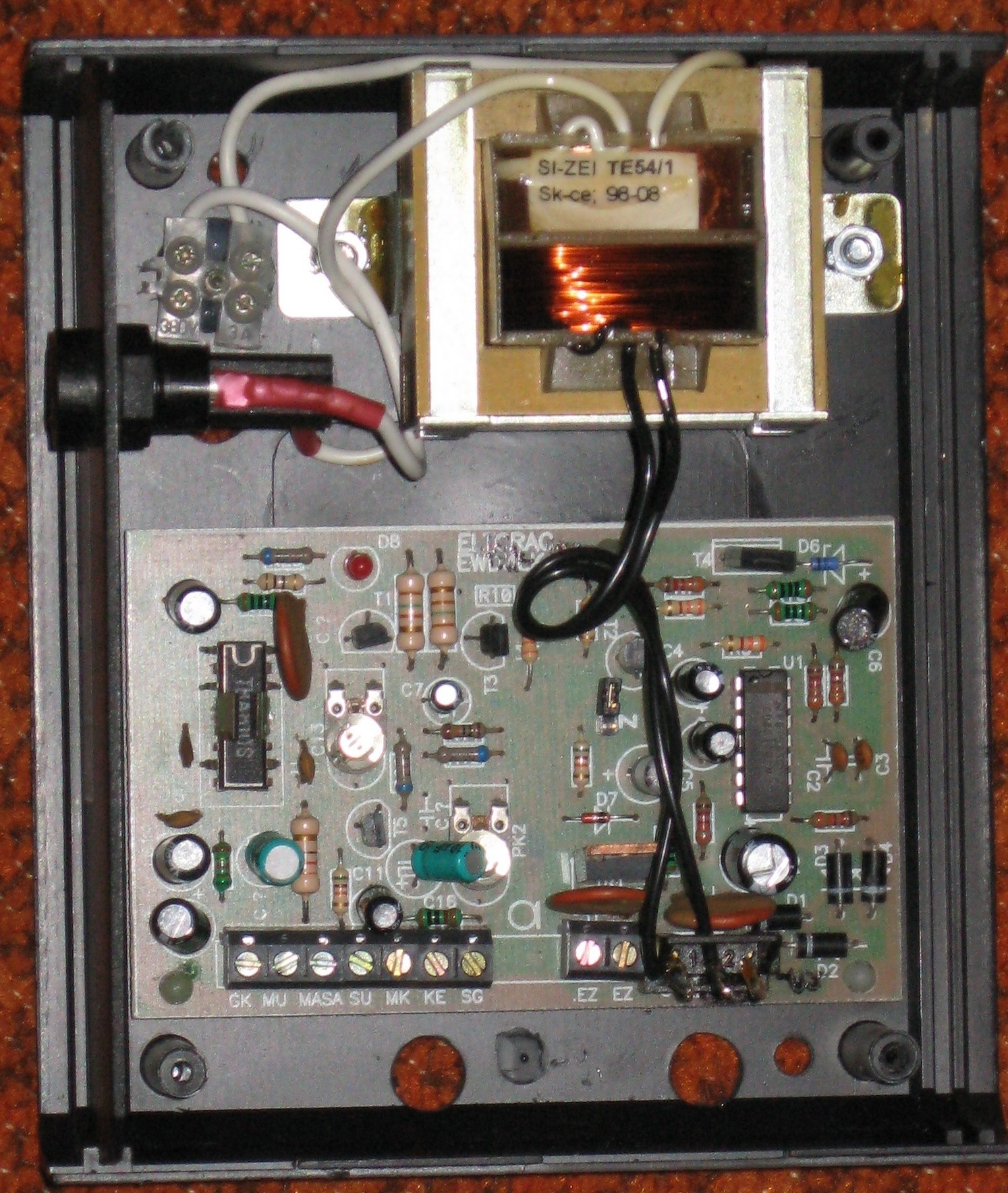
- Photo of this board with all cable removed.
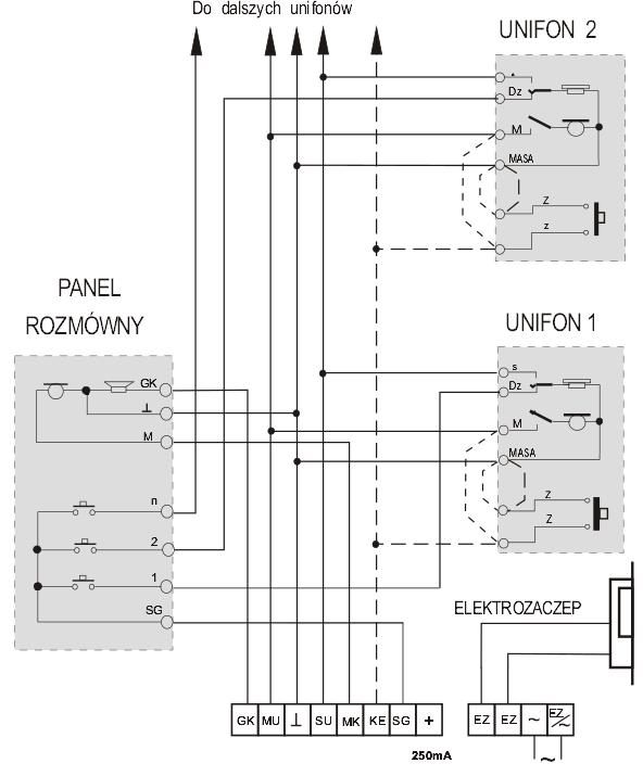
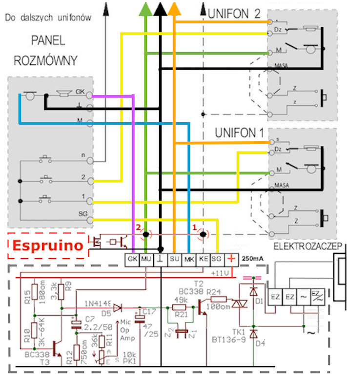
- Schematics of correct connections.
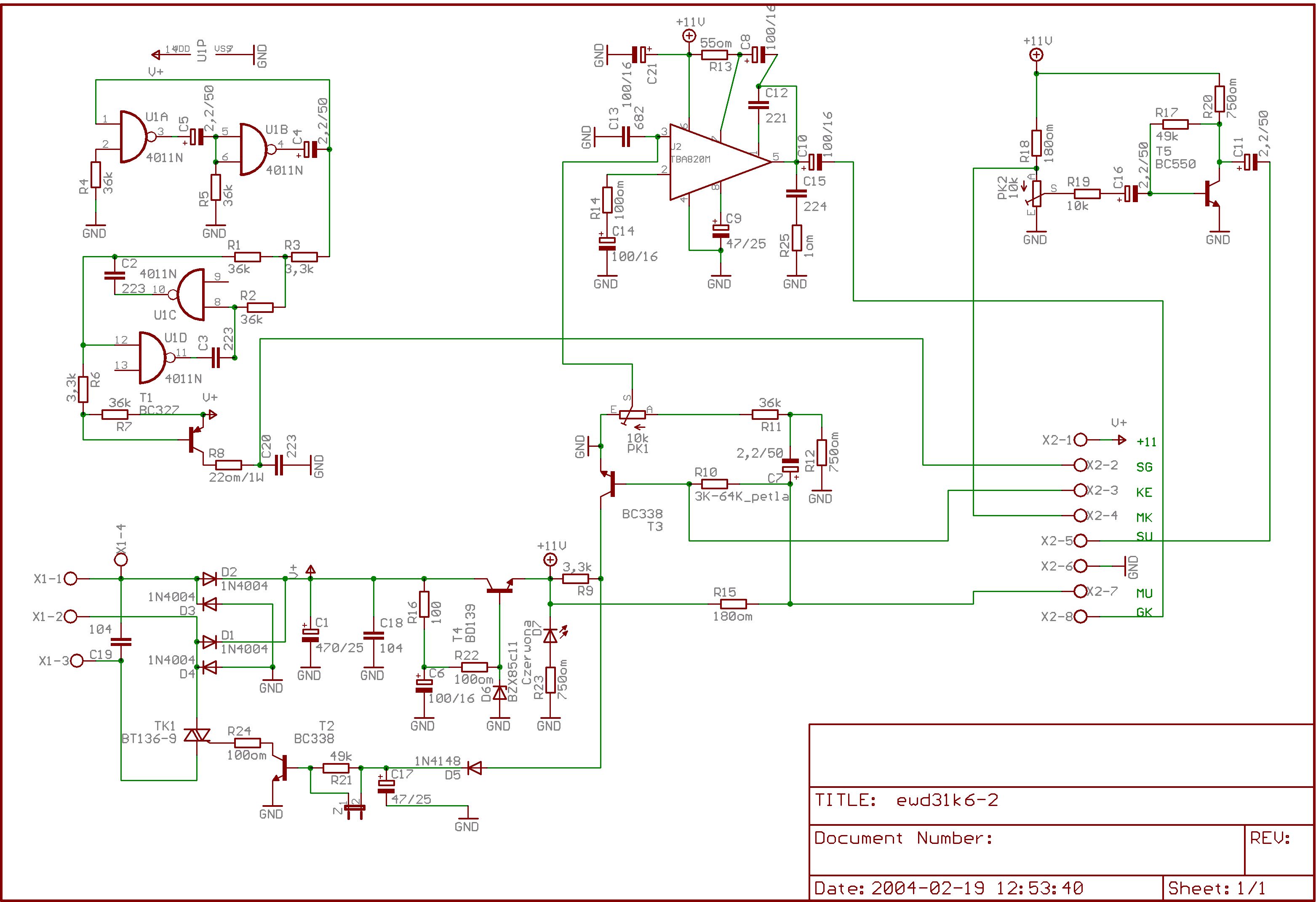
- The schematics of the generator.
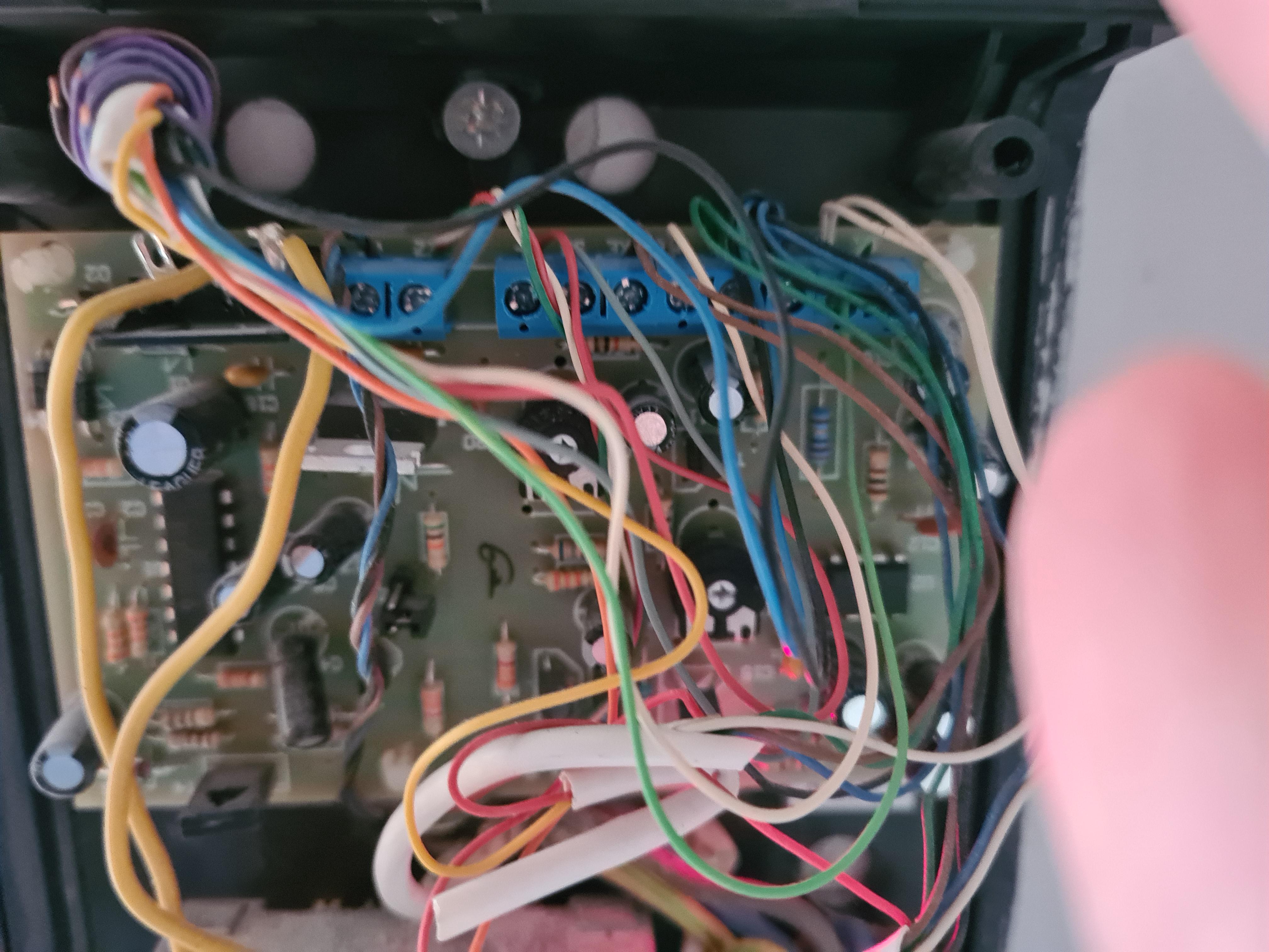
4.The photo of the actual wiring. It's cluttered and messy.
Unlocking action is triggered by shorting the black and brown cables.
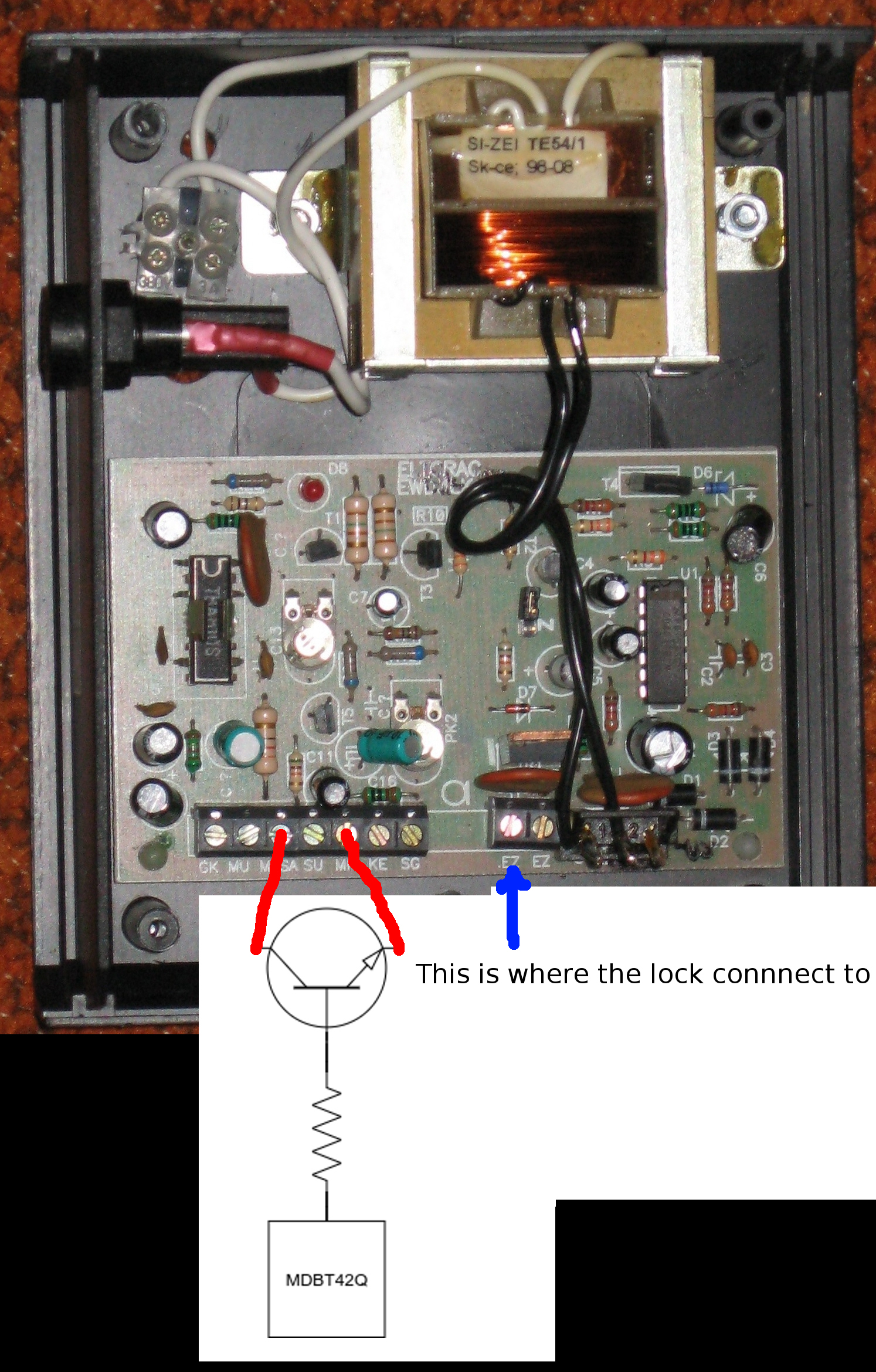
On picture without wires these are labelled MASA (this is polish for ground, black cable) and MK (brown cable).I figured this part out by inspecting how unifon in my home is wired. Also I shorted these two clips with a cable and it opens the lock. I measured there is 0.6V between these wires.
Thank you again for helping me with this :)
4 Attachments
- Photo of this board with all cable removed.
-
• #11
Sun 2020.05.03
Good Morning Marek and thanks for posting the images, I'll need to put a bit of time in to study.
What a treat, the link to the ElectroBoom channel. No I haven't seen that, but just took a quick peak at the channel intro. See a pattern here, First blowing up electronic products, then blowing up oil tankers, what's next?? Having a daily dose of those will make things more bearable!! ;-)))
A quick peak at the schematic and we are dealing with 11V there, so we'll need to be extra careful before connecting our precious Espruino. What an odd value, eleven. What is your mains voltage in your country? We're at 60Hz 120VAC and 5V and 12V are our usual standards. First time I've come across eleven.
The photos really help, any chance you could post one (or a really well understood label reference) of the actual wire you use and where it is bridging pins please. I imagine its on the black or blue terminal block. Where is the lock in the diagram and which pins is that connected to?
This will help others, and I know there are a few forum posters on your side of the world that are heavy into electronics and may have the rest of their day to help out, and I wanted to get this posted to allow a bit of time to get the jumper image posted for them.
P.S. make sure the photo is taken with the power off, otherwise I'll be watching your surprise on that ElectroBoom channel !! wink, wink
-
• #12
Good morning Robin :)
Ok so it's a little bit hard to make a photo of what I'm shorting in the box, because it's a huge tangle of cables and I can't seem to take a good photo of.
Instead I used the photo with all cables removed and added schematic of how I think I should connect. Please find it attached. I also marked where the electric lock is connected to (EZ label). However I would prefer not to interact with this part. The cables I want to short imitate human pushing the button on the Unifon to open door. The intercom generator controls the time the lock is unlocked. Even if I short it only for a fraction of second the door is unlocked for like ~5 seconds. That's a behavior I like and I want to keep when I trigger opening from Espruino :)
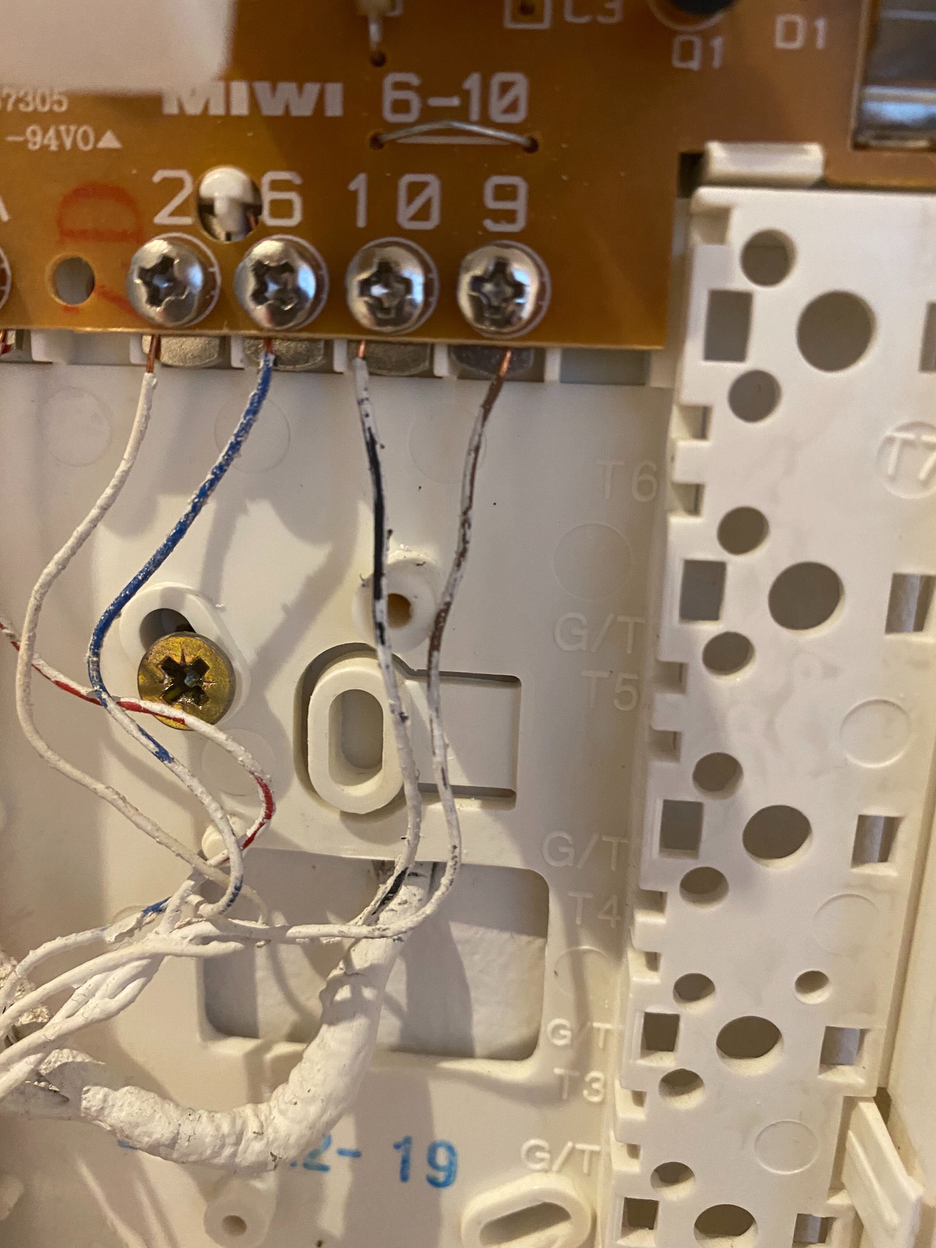
Also I'm attaching the photo of the Unifon internals that helped me figure out what I should be shorting. It's much clearer. On that photo I was shorting inputs labels 10 and 9. This is what allowed me to figure out the colors of cables that I should be shorting downstairs.
What is your mains voltage in your country?
I'm in Poland and the AC standards is 230 V / 50 Hz. Despite my googling effort I can't find what the standard for DC are. I begin to think there is no standard and engineers just make it up as they go:)
-
• #13
Gush, didn't add attachments. Fixing it.
2 Attachments
-
• #14
Sun 2020.05.03
Good Evening Marek and I realize this might not get to you tonight.
'the AC standards is 230 V / 50 Hz'
Well, that explains that humongous square boat anchor next to the fuse holder! Now when we brush up against 120VAC, it is annoying. I imagine you only ever touch 230VAC once!!!
'think there is no standard and engineers just make it up as they go'
Isn't that what they always do? They earned the piece of paper indicating they learned all the maths, so their right? ;-)
Do you have access to a voltmeter?As there is R18 180 ohm resistor connected to X2-4 MK then there should be around nine volts or so depending on position of PK2 10K ohm.
Initial impressions are that the collector and emitter are reversed in that diagram. I need more time to study.
See heading 'Transistor Switch' halfway down page
X2-4 MK would be connected to where the LED is in the diagram the collector. The emitter would connect to X2-6 MASA
R18 should protect the transistor collector, otherwise we may need an additional resistor there. Make the resisitor on the base 5K to 10K or something around that. Then don't connect to the Espruino MDBT42Q just yet. We'll connect a piece of wire in place of the Espruino, our human version to that base resistor and just touch it between X2-6 ground and X2-1 the 11V supply. This should toggle as if you were using the wire only method. Lets get that to function without smoke, then off to the fun part connecting the Espruino and writting code.
@allObjects would you agree on that assessment? I'd use a generic NPN 2n2222 as there are inexpensive. (or T5 BC550 should that be common) I know you always have the best diagrams, otherwise I'll have to resort to your famous ASCII method.
If that doesn't pull X2-4 MK to near ground, then we may need a slight modification to where the collector is tied to.
-
• #15
Hey Robin,
Thank you for your suggestion on how to test it without endangering MDBT42Q.
I will try to do some shopping for parts tomorrow and give it a try in the evening.Do you have access to a voltmeter?
I do and I was trying to confirm your deduction of what the voltage drop on R18 is. Unfortunately to no avail. I have a trouble identifying this resistor. Unfortunately the labels are just below of them and are not readable. I was trying to recognize it by the color code, but also there doesn't seem to be any that has brown-gray-brown.
If you could pull the circuit out I could inspect the connection on the bottom side, however this is out of question - as I'm not sure I would put it back together :)
Do you have an idea which resistor would it be on the photograph without the wires?
it between X2-6 ground and X2-1 the 11V supply
Just to confirm, the X2-1 will be the black slot with label "1" on top - the one on the bottom of the picture to the right of the slots labeled "EZ". I'm I right?
Thank you Robin :) Have a good night!
-
• #16
Sun 2020.05.03
Thank you for making the observations and taking the time to poke around a bit. Three points to review, and to make sure we are both communicating.
Is the voltmeter an analog needle type or a digital LCD type? Black ground and Red positive probes?
Regarding R18
If one takes a look at the schematic upper right, R18 connects one side to the positive rail 11V and the other to supposedly the end of a potentiometer. The trace exiting to the left runs down to X2-4 MK where the drawing of the emitter is now connected. I say supposedly, under the assumption the resistor running E-W just above KE and below the silk screen C16 is the 180 ohm (brown-grey-black with black zero multiplier - color too off to be sure) appears to connect to the wiper of PK2, as it is immediately centered between the tabs of PK2, those being just North of the pot itself. Having access to the underside would be nice to verify but isn't necessary. So, electrically, the screw terminal MK is the same point as where the vertical trace in the schematic connects to R18. Then placing the black ground probe to MASA and red positive probe to MK should provide est 6-9V which is actually the drop across the pot, but would provide the value at R18. Would like to confirm so that we know what the transistor is connected to and the range it will be swinging.'Just to confirm, the X2-1 will be the black slot with label "1" on top'
I'm glad you pointed this out, as I didn't double check the schematic terminal block X2. The schematic seems to be for the board with the blue terminal block as it has eight pins. The photo with the black terminal block only has seven. It appears that is a variant or a knock off of the original. Double checking the schematic, I missed that X2 has eight pins, but the board only has seven screw terminals. The big mystery, where is the positive 11V X2-1?
Glad you pointed that out, but don't have a good idea where to get at the 11V yet. I'll continue to study.
Now the two black wires dropping down from the transformer are the input to the AC section which is mostly the parts to the lower right of that circuit board. D1-D4 are the bridge rectifier converting the AC to DC. The labeling 1 and 2 are likely what we see on the left side of the schematic as X1-1 and X1-2. (also not exactly matching) Putting the voltmeter in the AC position on a 20-50VAC scale and on each of the black wires will probably show est 12-24VAC as a S.W.A.G. (silly wild arse guess) and would a connection bewteen MASA and that pin 1 been made, wouldn't have been wise and we might have seen you in the next ElectroBoom episode as we would have been grounding one side of the inbound AC wave. Electrons would not have been happy. Very excited though! Depending on the meter type and which scale it was on, might have damaged it.
It's likely that C16 and R17 are part of the five second delay you mentioned with PK2 adjustable for that delay interval.
Curious, what is the voltage between MASA and X2-7 MU ? (11V ? maybe)
As that pin is connected to R15 180 ohm and then to the other side of the LED, (which by the seems to be labled backwards as the anode side is to ground, so I don't see how it could ever illuminate - me thinks schematic backwards) we may be able to use that as the trigger point for our base resistor input. For an NPN we will need a positive voltage greater than the drop across it's emitter to turn it on, the equivalent of when you were just using the jumper. The emitter would need to connect to MASA though and it's collector to MK at around 6-9V When the transistor is on, we'll have 11-0.7V / 180 ohm or 57 ma current through it. Just over a half watt, but a brief interval, shouldn't be an issue. But R18 in the photo looks like just a quarter watt, can't be sure size wise. -
• #17
From what I understand this is - mainly - going on: pulling
KEto ground will shut of Transistor T3, turn on Transistor T2 and Thyristor TK1. Usingoutput_pulldownon Espruino will do the trick on controlling NMOS FET or NPN Transistor. Connecting Gate or Base respectively with a 22k..47K helps to not have an open input in case Espruino is not powered (most darlingtons have already a built in resistor doing so). A plain "output" (or "open-drain") for pin mode is then good enough. Attached schema shows only relevant components.Alternative, the dashed connections to a door open push button in the Unifon in conjunction w/ C7, R11, R12 and PK1 allow to 4-wire only vs. 5-wire Unifon operation and makes the Unifon Mic input line do double duty:
- Unifon Mic signal adds AC component to MU (Mic Unifon) DC input signal. The AC part is coupled out over C7 to input of OpAmp which drives the Panel Speaker. Potentiometer PK1 (with R11 and R12) is used to adjust OpAmp input to the DC component (Mic button pressed, no speaking going on).
- Pulling MU down - DC ground - also grounds 'input side' of R10, and with that also Base of T3, just like grounding Base of T3 directly by pulling KE to ground. R15 / 180R is then taking all the brunt of the 11V. With about 61 mA current it burns - momentarily - about 0.72 W power and is therefore the fat resistor, compared to the other ones, which are skinny. Quite a resourceful solution, because the Unifones can be run with just plain 4-wire phone cable... ;) - EDIT: I don't know about the Z1-Z2 Jumper which is open in the pictures. It could be that it has to be closed for option 2 to work.
For sure Espruino should not be connected directly to KE nor to MU - not on KE because voltage is way above 3.3V and you do also not want any noise on the pin from house wiring either. (@MaBe: sorry, this time no char graph schematics either); not on MU for same reason and could anyway not handle draining 61+mA. But what you can as added bonus: power Espruino MDBT42Q Bluetooth Breakout Board from the + (11V) of the control station... ;)
So, you have two options to make the unlock solenoid work: Ground either KE or MU... with a NMOS FET or a NPN Transistor.
Thanks for sharing this nice thought exercise.
P.S.: Colors help me think...
1 Attachment
- Unifon Mic signal adds AC component to MU (Mic Unifon) DC input signal. The AC part is coupled out over C7 to input of OpAmp which drives the Panel Speaker. Potentiometer PK1 (with R11 and R12) is used to adjust OpAmp input to the DC component (Mic button pressed, no speaking going on).
-
• #18
Thank you @allObjects and @Robin for time you put into this :)
So indeed, all this time I thought that unlocking action is triggered by grounding MK. Analyzes of @allObjects shows that it should be KE. So I double-checked and you're right :) I was grounding KE and put wrong info in one of the first posts in this thread. To my defense this generator is installed in a place that is hard to get to, so I was relying on small mirror to read the labels.
In any case, it's definitely KE that is getting grounded.
I also did a bunch of measurements:
Is the voltmeter an analog needle type or a digital LCD type? Black ground and Red positive probes?
It's a digital LCD type, with black and red probes.
- The voltage drop on on R18 by measuring between MK and MASA. The voltage drop is 9.6V.
- The VAC between X1-1 and X1-2 (the black cables from the coil) and it's 13VAC.
- The drop between MU and MASA is 14V.
- The drop between KE and MASA is only 0.6V (this is what I need to pull-down to ground).
Does this information change anything in values of resistor or transistor type I should use ?
Today I got pulled into work and did not manage to do the shopping. Hopefully tomorrow I will go buy the missing parts :)
Thank you both for all your awesome help:)
- The voltage drop on on R18 by measuring between MK and MASA. The voltage drop is 9.6V.
-
• #19
urvw. Consuming the schematics gave me some ideas how to control AC loads / devices w/ Espruino... a win-win.
To answer your question: nope, no change in what you need. Since you may do soldering anyway: do you not have some old electronics that you could cannibalize? Practically any small signal transistor will do... and you will also find enough resistors to accommodate what ever needs you have. Last but not least electronics that has to go - because it is already gone - is of older, still is of thru-hole components technology.
Do your Unifones have the momentary push button installed and wired up? And if so, I assume it is 4 wires only based on the pictures you uploaded.
-
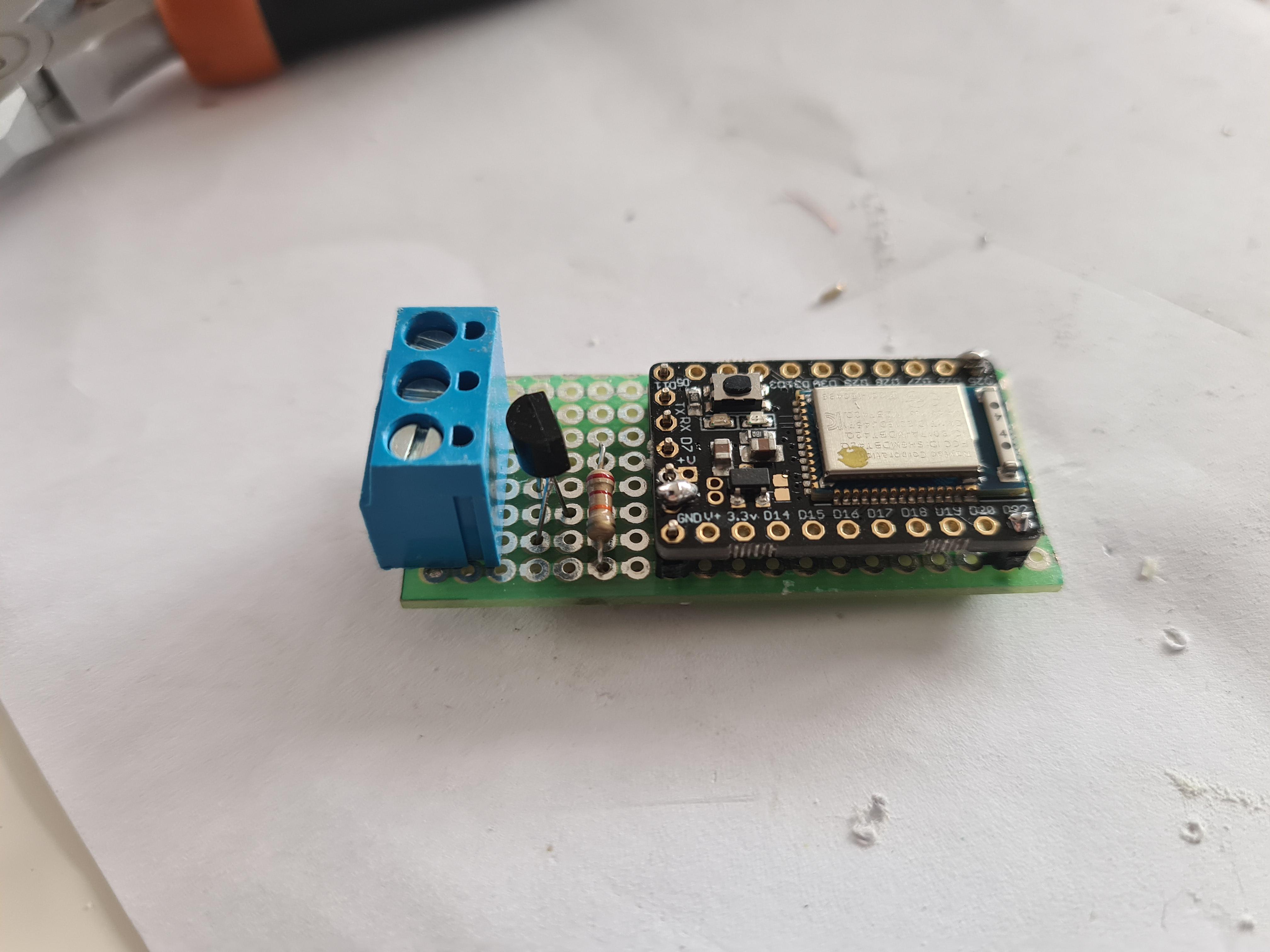
• #20
It's taking shape.....
1 Attachment
-
• #21
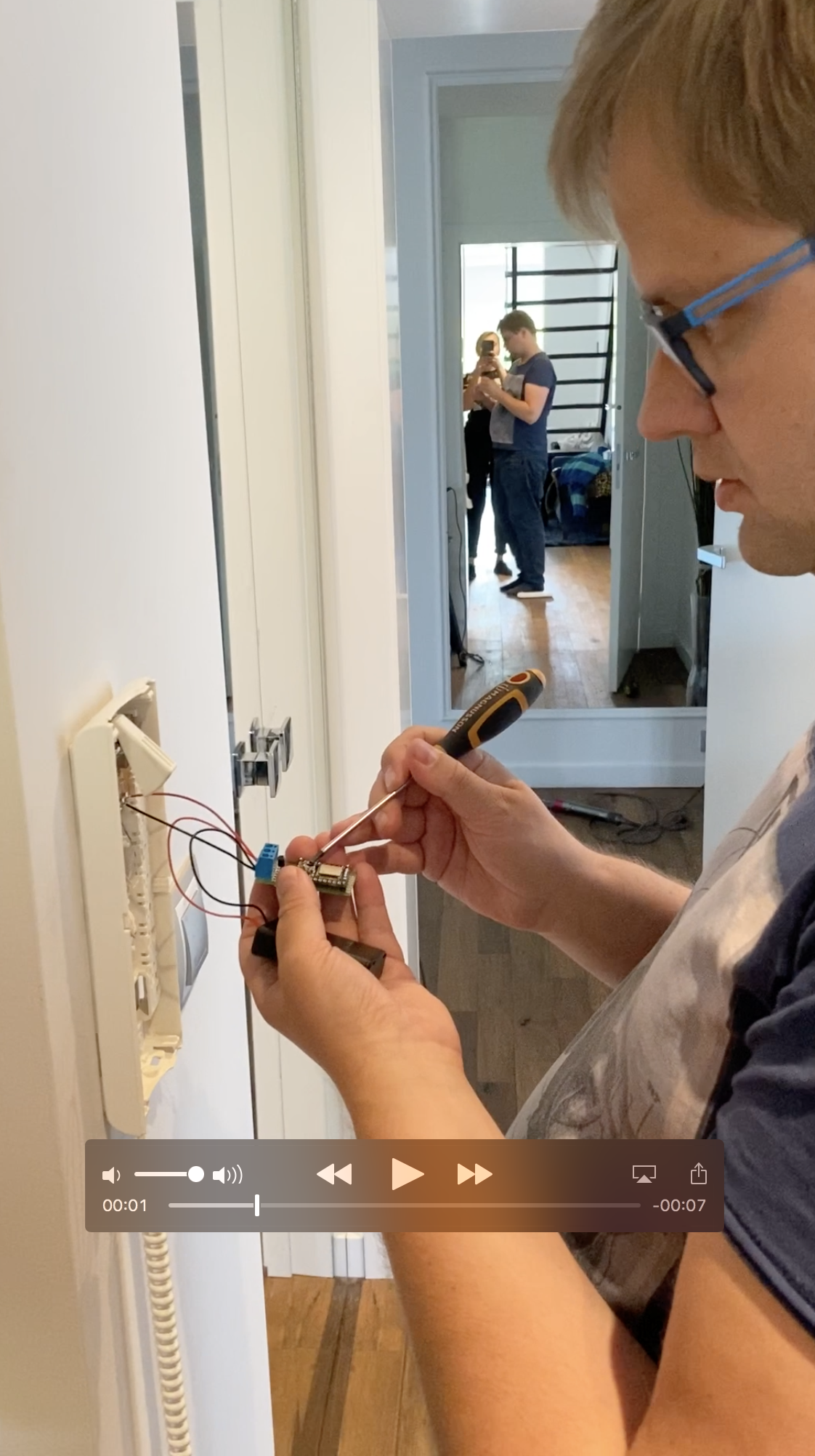
Successful test :)
Now off to coding part (controlling this via BLE from mobile device).
Thank you @Robin and @allObjects :)
1 Attachment
-
• #22
...thanks for the feedback... great recording with the mirror... double the success and excitement... I had to make a shot. (I assume the black box in your hand is the power supply: batteries).
1 Attachment
-
• #23
That's correct, it's a battery pack, for 3 AAA bateries.
The idea is to eventually power the curcuit from MK connector where I measured I have +9V.
On the video I'm only making a test taking advantage of the fact that in Unifon I have access to same cables so I don't need to take the stairs ;) -
• #24
Looking at the wiring and PCB schematics, adding something on MK / powering something by it does not seem to be the best idea, because it interferes with the panel microphone's hot end...
You posted pics of two central unit. I assume the wired one is the one installed in your place. It has actually a screwable connector in the blue block (next to the block with the Z / lock electromagnet connectors), marked with a + in the wiring schema, which brings the +11V out. The printed schema says 11V on X2-1. The second one does not bring out the 11V.
 Robin
Robin user112057
 allObjects
Hi,
I'm working a small project just for fun. I'd like to open an electronic lock through BLE using MDBT42Q.
The unlocking action is triggered by closing circuit between ground and another wire.
I have though I would be able to connect these two wires to some PINs in MDBT42Q brakeout and open circuit between them programatically.
However it doesn't seem to work like this.
Can anyway give me a hint of what is the best way to interact with such circuit from MDBT42Q?
Thank you,
Marek Kowalski