-
• #27
Ok, so here is was I have for the pin maps. As I say, I've taken the Adafruit CC3000 shield as an example, and ensured that should work be mapping those pins, the rest I have taken the best options available based upon the functions from the various pinout diagrams. The only area that is marginly "weird" is between arduino pins 2 to 5 where we have to use a few non-consective numbers together, but this is based upon the Arduino CC3000 pinout and the Espruino CC3000 requirements.
Other than that, can anyone see any glaring issues?
Matt
1 Attachment
-
• #28
The capacitors for the L7805 is there for stability.
-
• #29
So this is what I've got so far. I've mapped everything as per the previous map spreadsheet and have added a screw terminal to attached 5v power (I haven't yet added a voltage regulator yet). I've also added a power jumper to allow the 5v to be sent to VBAT in order to power the Espruino too. I've purposefully located the screw terminal in front of the power socket on the Espruino to prevent 2 power supplies being attached at once.
So, my last question. What do people thing regarding the 5v regulator? If we used a L7805, this would require a minimum of 7v to be supplied right? Plus would need space for a heatsink. What if someone wants to connect a 5v supply direct? Has anybody got any other suggestions for regulating the voltage? or should we just have the screw terminal and say "make sure you attached a regulated 5v supply"?
Matt
1 Attachment
-
• #30
Hi Matt, As far as I know the 7805s do need some capacitors - even if they're only small. I'd check the datasheet for sure though. As far as heatsinks, you could just make sure there's an area of copper on the PCB, and could fold the 7805 over and bolt it onto the shield. Not that they'd get that hot unless you're drawing a lot of current or powering from a very high voltage,
I guess you could put a USB socket on it? that would ensure people only used 5v regulated supplies.
By the way - the 5v->VBat jumper will have the effect that everything will be powered up via Espruino (only at ~4.3v though) when you plug it into USB. It might be quite handy...
-
• #31
Cool.
I think I might need to change a couple of things. I think i need to add the voltage regulator in between VBAT and 5v, rather than on the 5v line. Also, if we want to be able to power the 5v pin from the USB connected to the Espruino, I might also need to add another jumper to allow the voltage regulator to be bypassed (ie, if you already have 5v coming from USB, you won't want it going through the regulator again).
So close...
Matt
-
• #32
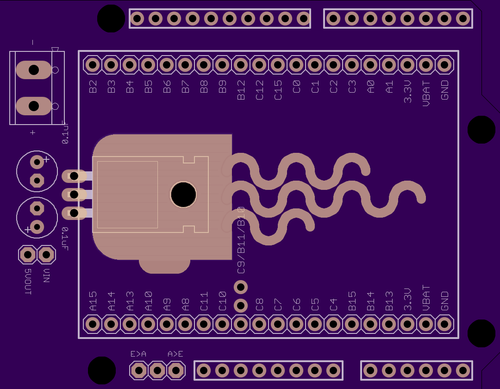
Thinking of where to put the LM7805, do you think it would be safe to put between the adapter / espruino if it's sat on a copper pad (like the attached)? I just remember these things getting pretty hot, so don't want to do any damage to the Espruino (especially given the Espruino chip will be directly above it).
Matt
1 Attachment
-
• #33
I'm sure that'd be fine... Those regulators won't get crazy hot unless you draw a lot of power...
I'm not sure which schematic package you're using, but something like Eagle lets you basically flood-fill copper in an area, which will let you easily get the maximum amount of heatsinking.
-
• #34
Almost there (need to double check the polarity of my capacitors on the voltage regulator).
I've just been trying to get my head around the various power options which I think I now have. If you look at the attached, I've now got a few jumpers defined. The one next to the voltage regulator lets you bypass it, so if you do feed it in a constant 5v, you don't have to loose volts going through it.
The other set lets you define whether power should come from the Epsruino to the Arduino shield (E>A), or whether power to the Arduino Shield should flow to the Espruino (A>E).
So, these are setup as follows:
A>E
V+ > VIN Pin > Voltage Regulator > 5v Pin > VBAT EspruinoE>A
VBAT > VIN Pin > Voltage Regulator (probably set to bypass) > 5vSo by always sending volts in to the vin pin, then to the regulator, you can always power the arduino shield directly from the vin pin aswell, and it will still get regulated.
Obviously, if you jumper both at the same time, or opt to bypass the regulator whilst supplying more then 5v, you run the risk of damage, but I guess this is just down to people being careful?
So, can anyone see any flaws in my logic?
Cheers
Matt
1 Attachment
-
• #36
Looks good - I think you get what you deserve if you start shorting stuff out with Jumpers :)
You could potentially get rid of VIN/5V jumper now you have the E>A and A>E jumpers. I think just putting a jumper sideways along the bottom does the same thing? I guess a little graphic on the silkscreen would be helpful:
..
--  Vin-5V

|.
|.  E > A

.|
.|  A > E

||
||  All 5V
Not that my descriptions are helpful, but you get the idea :)
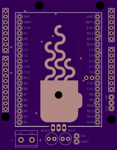
By the way, yes - Coffee would be neat :)
-
• #37
Ahh, cool, didn't spot that one. I take it this would require someone to solder the pins? I tend to like to keep things temporary if possible, so you can always use it the other way more easily.
I was actually gonna look at swapping the bank of 4 for a bank of 3, so you couldn't have both E>A and A>E at the same time.
I'll post up another pic in a bit.
Matt
-
• #38
Playing with the heatsink :)
1 Attachment
-
• #39
So, here it is. I think this is just about everything. I'm gonna wait till my original (proto board) arrives, and wire it up the same so see if everything works ok. Once I know it does, I think it's good to go :)
1 Attachment
-
• #40
I would happily do some testing of this board if needed. I have quite a few arduino shields including the GSM shield which is the most temperamental of them all power wise.
-
• #41
@Hardware_Hacks that would be awesome. I've uploaded it to OSHPark if you fancy ordering one.
https://oshpark.com/shared_projects/0G2YdWHD
Do let me know how you get on.
Matt
-
• #42
Sounds good will take a look at getting one now (Their site seems a little broken at the moment though for me..)
Is minimum order quantity 3? Don't think I'll need 3 if it didn't work :p
-
• #43
@Hardware_Hacks yea. There is ringworm in the UK, but seems they are similar priced for just one.
I guess I could always order a set of 3 and just send one to you for testing :)
Matt
-
• #44
Let me know if you have/haven't ordered one and I'll order them myself.
Matt
-
• #45
Hey matt
I haven't ordered one yet as I had the slight hiccup of snapping my USB connector on the espruino last night so have a replacement on its way.Have you had chance to test your initial board wiring as mentioned a few posts back?
-
• #46
Heard about that. Gutting! Hope you get it sorted.
Havent recieved my protoboards yet, just got confirmation of them being shipped yesterday, so hopefully some time next week.
I'll get some of these ordered though. Im pretty happy with the wire routing so it just needs testing really. I'll give you a shout when they arrive and send one over to you if you don't mind giving it a run through its paces?
Matt
-
• #48
I don't think so - it's mostly FUD. As I've said before, Espruino is 5v tolerant for inputs, and most logic inputs of shields will still accept 3.3v inputs.
If you really wanted you could add pads for SMD pullup resistors (that pull up to 5v) as then you can stick Espruino into Open Drain mode and get a full 5v swing... however folks could just solder resistors onto the back of the board for the few pins where that may be required.
-
• #49
Sounds good to me I'd be more than happy to give it a test
-
• #50
@Hardware_Hacks I have some boards on order now. I'll give you a shout when they arrive.
Matt
 mattbrailsford
 Frida
Frida Gordon

 Hardware_Hacks
Awesome! I think I should be able to get this nailed tonight then :)
Regarding the 5v regulator, I do have some spare L7805's here. I've seen a few circuits for these using capacitors between the pins for protection. Am I right in assuming these are for AC currents? and given that these boards should only ever be driven by DC currents, should it be ok to leave them out if I want to incorporate a 5v regulator into the board? (I might add a button too :))
Cheers
Matt