-
• #2
Sat 2020.10.03
For those following along; HD44780 LCD Display
Hi @user118421 and thank you for the images.
From:
It appears the pull-ups are on B7 and A8, and not B6 and B7
Could a quick cross check verification be done. Hey, who moved that pin row since the last time I remembered where that pin was actually located?
-
• #3
Hmm, is this a new version of the HD44780 that operate with 3v3?
AFAIK it is a 5v device.
-
• #4
Good spot @MaBe! My orthagonal viewing glasses didn't pick up on that in addition to B7-A8. ;-)
As the USB connector is supplying the 5V, it appears 3V3 is available after the regulator as the VDD output pin3.
https://github.com/espruino/EspruinoBoard/raw/master/Pico/pdf/schematic_1v3.pdf
-
• #5
Thank you very much for helping!
The pin mistake is embarrassing, unfortunately correcting it did not help, still same error. Does the 5v requirement mean I cannot use this display with the Pico? The datasheet seems to me to suggest that either 3.3v or 5v can be used but that’s probably just me not understanding how to read it. I tried connecting the HD44780 to an ESP32 as well as it has a 5v pin but no luck and also tried a Nokia 5110 to the Pico according to instructions but nothing happens. Probably just me doing something wrong but then maybe I could at least stop trying to connect a HD44780 to the Pico?
-
• #6
Vbat is in your case 5v from the usb connector.
Remove the additional pull ups, because there are 4k7 added to the backpack.
-
• #7
Thank you, that is good to know - sorry for being so ignorant, total beginner :)
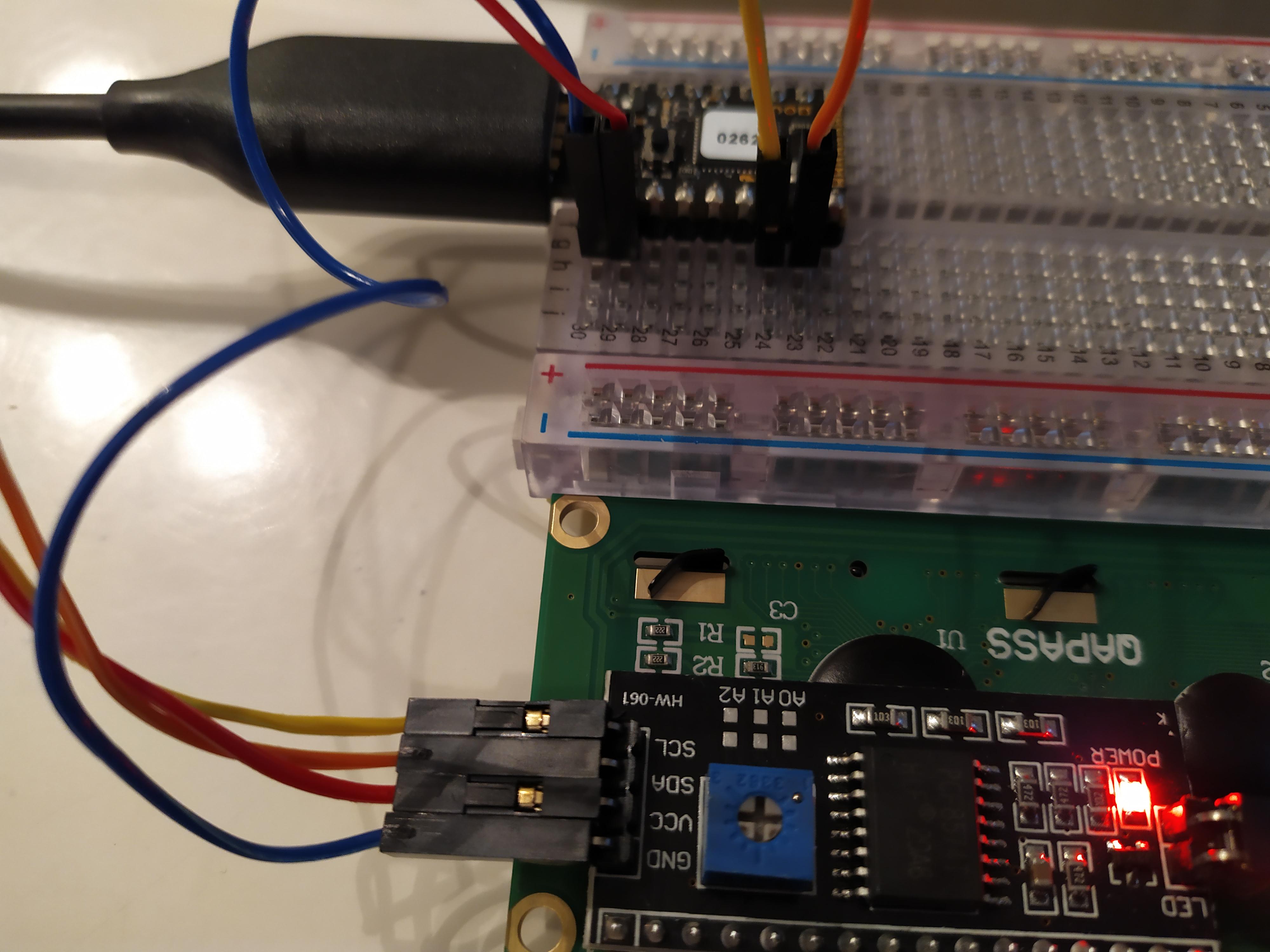
Should I then simply wire as in this picture?
I2C <-> Pico
GND <-> GND
VCC <-> VBAT
SDA <-> B7
SCL <-> B6I still get the same error though..
1 Attachment
-
• #8
Hmm, just double checking pins and HD44780 documentation
Yellow - SCL1 - B6
Orange - SDA1 - B7Please try this snippet - hope it works for you.
I2C1.setup({scl:B6, sda:B7}); // PCF8574AT based IO expanders default to address 0x3F var lcd = require("HD44780").connectI2C(I2C1, 0x3F); lcd.print("Hello World!"); -
• #9
Unfortunately it gives almost the same error, except these two lines;
in function "connectI2C" called from line 4 col 51
var lcd = require("HD44780").connectI2C(I2C1, 0x3F);
|_| espruino.com 2v07 (c) 2019 G.Williams >Uncaught InternalError: Timeout on I2C Write BUSY at line 2 col 13 g|4,g|4,g,g]) ^ in function "a" called from line 1 col 7 a(51,1);a(50,1);a(40,1);a(12,1);a(6,1);a(1,1);return{write:a... ^ in function "h" called from line 2 col 15 g|4,g|4,g,g])}) ^ in function "connectI2C" called from line 4 col 51 var lcd = require("HD44780").connectI2C(I2C1, 0x3F); ^ Uncaught Error: Cannot read property 'print' of undefined at line 5 col 4 lcd.print("Hello World!"); ^ -
• #10
Sun 2020.10.04
I agree with you that; that #5 post specific document does present some confusion over the allowed voltage. It is also very specific that the LCD requires 5V. Without that board schematic, it would be guessing as to whether a boost converter is onboard to create the 5V when using 3V3.
While I'll have to defer to the board designer for a definitive explanation, the Pico schematic implies a small drop over the FET when attempting to pull power, when not supplying at pin 18 BAT_IN. I just measured my Pico using USB power, but with no load, and pin 2 is at 4V6 which is very close to the low end specified to even drive that LCD. Under the assumption that speification sheet is in error, any luck driving from the regulated 3V3 pin 3 as was done in the initial post? (not expecting success however)
As all the Arduino snippets and the Espruino documentation example are suggesting 5V, I'd first check to see if that is what is at pin 2 as is now wired in a loaded condition.
Regarding #7 image and #9 code snippet, SCL and SDA now appear to be wired as needed. Does the same error exist when removing the
lcd.print()line as a possibility to see if I2C comm is occurring during initialization with just the connect function? On a really long shot, I've gotten a few knock off boards (not this module) that have had reversed silk screen. Something to consider, but not likely. -
• #11
Many thanks for all help!
When I measure the I2C receives 4V4 from VBAT so maybe that's not sufficient.
The 3.3 pin did not work either.
Removing the the print line still leaves me with the same error (except of course the part related to the print command).I really don't care about this specific display but as it failed just like the Nokia 5110, is there any specific LCD display you can recommend that you know will work with the Espruino boards?
-
• #12
Thank you for the voltage readings @user118421
'Removing the the print line still leaves me with the same error'
As the errors bubble up, and therefore appear in reverse order, I would have expected a slightly different output, as the specific error related to calling the print() function is now not present.
Did you mean the same as in only the same for the first two line code block from #9 post perhaps? (I was attempting to determine if I2C was initializing [it's overhead] error free before attempting comm over the I2C bus)
Under the assumption 5V has to be the minimum input voltage, any other way to supply that, or only just the USB cable available at the moment?
'this specific display but as it failed just like the Nokia 5110'
Do we have a separate issue here with the 5110? There is a tutorial, but that is based on SPI rather than I2C.
I'm not a fan of using cutting edge builds for the existing tutorials, but as a consideration, would flashing to a previous version have a different outcome?
I have not tried or tested, but it might mean an additional step is required. I'll defer to others for this: (see code block under the schematic, beneath heading 'Power, and the FET/B0 Jumper')' Once the FET/B0 Jumper is shorted, the following commands will work:
digitalWrite(B0,0); // Turn on the 'Bat' output fully '
I'm not sure if 'Bat' means the VBAT pin 2 output, what the voltage might be, or whether this implies just a current boost. . . . -
• #13
Once the FET/B0 Jumper is shorted, the following commands will work...
Don't do this! It's for something totally unrelated (allowing you to use the FET not to gate USB power, but to control other stuff). But because you're using USB you need it non-shorted.
My memory of the HD44780 boards is that generally the I2C actually worked ok at 3.3v, and the backlight lit up, but nothing was displayed on the screen - hence the need for 5v. But the 4.4v you have should be fine. I've used those exact displays on the Pico before without issues.
I guess it might be that you need the pullup resistors to 3.3v, now it's running from 5v?
Even before you add pullup resistors, please could you try:
var i = new I2C();
i.setup({scl:B6, sda:B7});
// PCF8574AT based IO expanders default to address 0x3F
var lcd = require("HD44780").connectI2C(i, 0x3F);
lcd.print("Hello World!");
also try changing the
0x3Fto0x27if that doesn't work (just in case).Software I2C can use the chip's internal pullup resistors, and so may be more able to communicate properly.
-
• #14
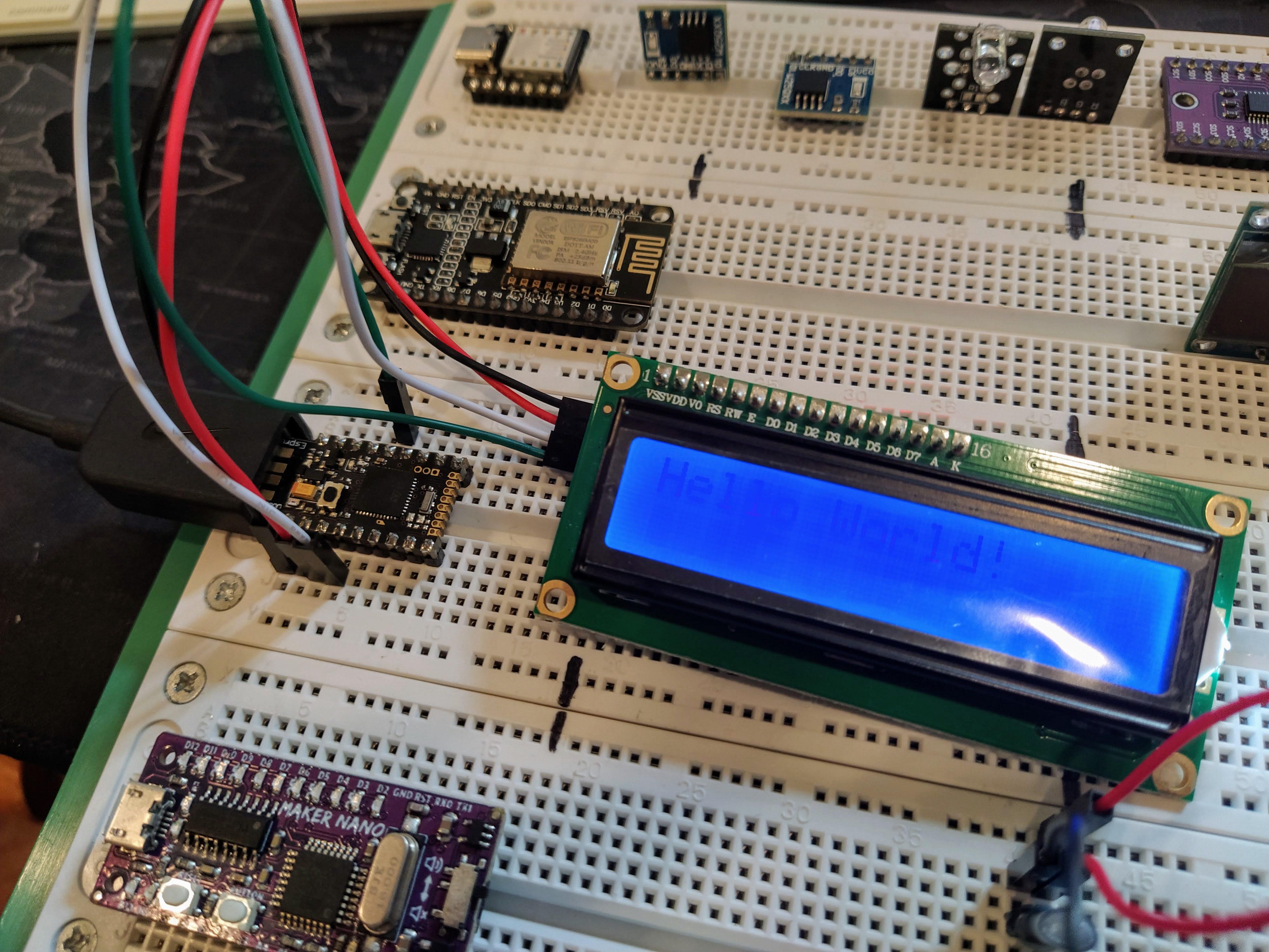
I just tried it out on my pico (pardon the contrast, but the Hello World is there)
However, I could only get it to work with I2C2
If I use I2C1 b6/b7 I get this error:
Uncaught InternalError: Timeout on I2C Write Transmit Mode 2
 at line 1 col 111
...|4,a|4,a,a,d,d,d|4,d|4,d,d])
                              ^
in function "a" called from line 1 col 7
a(51,1),a(50,1),a(40,1),a(12,1),a(6,1),a(1,1),{write:a,clear...
      ^
in function "a" called from line 1 col 133
...,a|4,a,a,d,d,d|4,d|4,d,d])})
                              ^
in function "connectI2C" called from line 1 col 807
...('HD44780').connectI2C(I2C1);lcd.print('Hello World!')
                              ^
Execution Interrupted
Here's the code I used to test with I2C2:
I2C2.setup({scl:B10, sda:B3});
var lcd = require("HD44780").connectI2C(I2C2);
lcd.print("Hello World!");
1 Attachment
-
• #15
Tried it again on I2C1 b6/b7 , got a slightly different error message this time:
____ _ | __|___ ___ ___ _ _|_|___ ___ | __|_ -| . | _| | | | | . | |____|___| _|_| |___|_|_|_|___| |_| espruino.com 2v07 (c) 2019 G.Williams >Uncaught InternalError: Timeout on I2C Write BUSY at line 1 col 111 ...|4,a|4,a,a,d,d,d|4,d|4,d,d]) ^ in function "a" called from line 1 col 7 a(51,1),a(50,1),a(40,1),a(12,1),a(6,1),a(1,1),{write:a,clear... ^ in function "a" called from line 1 col 133 ...,a|4,a,a,d,d,d|4,d|4,d,d])}) ^ in function "connectI2C" called from line 1 col 807 ...('HD44780').connectI2C(I2C1);lcd.print('Hello World!') -
• #16
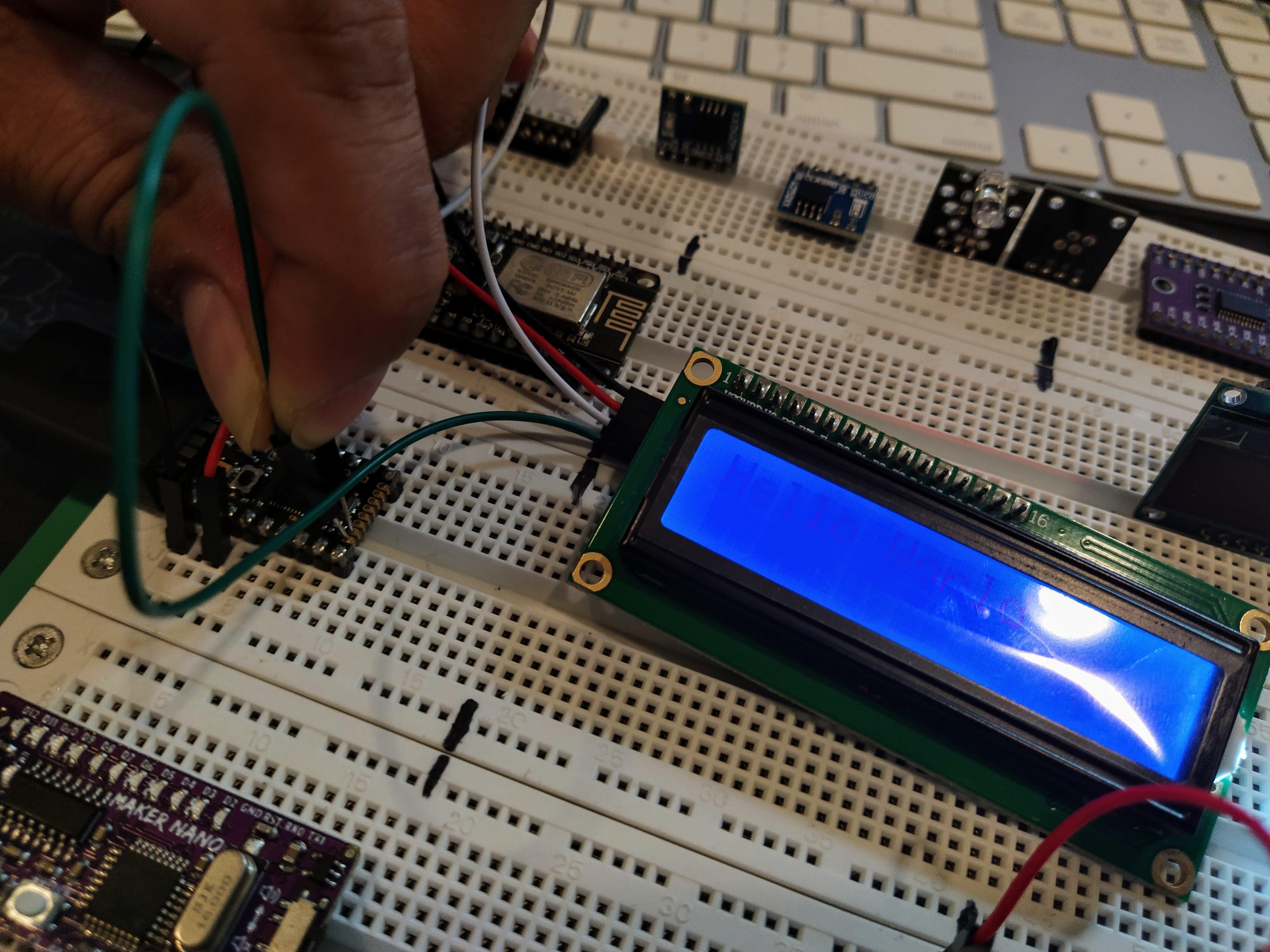
Doing it on I2C1 with B9/B8 works
1 Attachment
-
• #17
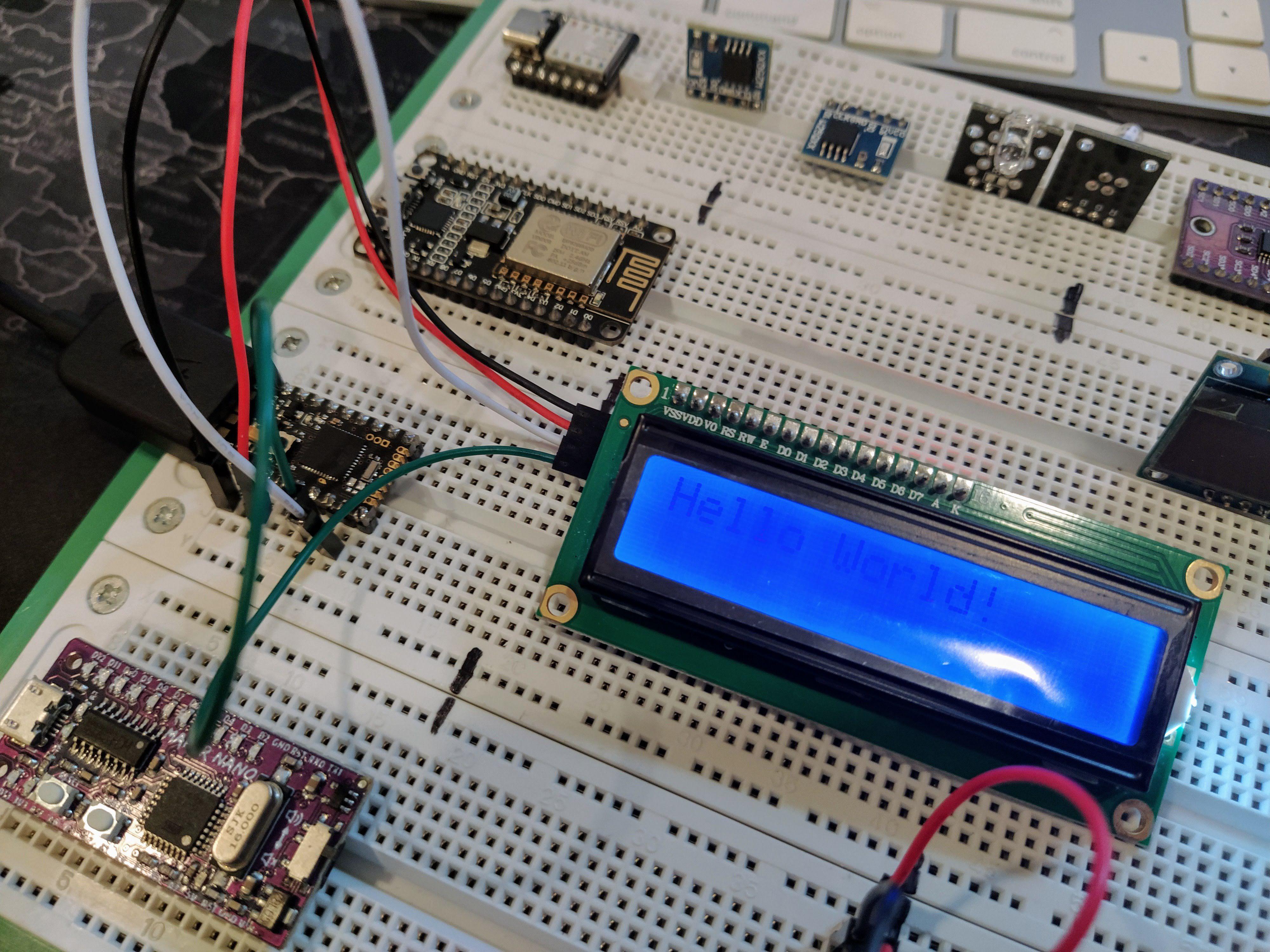
Using software I2C seems to work with b6/b7
var i = new I2C();
i.setup({scl:B6, sda:B7});
// PCF8574AT based IO expanders default to address 0x3F
var lcd = require("HD44780").connectI2C(i);
lcd.print("Hello World!");
1 Attachment
-
• #18
Great! I wonder whether this is actually some strange interaction with Serial1, which uses B6/B7 as a Serial port by default.
-
• #19
I tried
USB.setConsole(true)as well, as I saw the!on the pins but that still didn't work. So maybe b6/b7 just isn't suited for hardware I2C1 and instead just use the other I2C peripherals? -
• #20
Setting the console to USB won't actually disable the Serial port - so you wouldn't expect that one to work.
Serial1.setup(9600,{tx:...,rx:...});to some other pins might fix it -
• #21
Just tried this:
Serial1.setup(9600,{tx:A9,rx:A10});
I2C1.setup({scl:B6, sda:B7});
var lcd = require("HD44780").connectI2C(I2C1);
lcd.print("Hello World!");
And it's still the timeout error
>
 ____                 _
|  __|___ ___ ___ _ _|_|___ ___
|  __|_ -| . |  _| | | |   | . |
|____|___|  _|_| |___|_|_|_|___|
         |_| espruino.com
 2v07 (c) 2019 G.Williams
>Uncaught InternalError: Timeout on I2C Write BUSY
 at line 1 col 111
...|4,a|4,a,a,d,d,d|4,d|4,d,d])
                              ^
in function "a" called from line 1 col 7
a(51,1),a(50,1),a(40,1),a(12,1),a(6,1),a(1,1),{write:a,clear...
      ^
in function "a" called from line 1 col 133
...,a|4,a,a,d,d,d|4,d|4,d,d])})
                              ^
in function "connectI2C" called from line 1 col 842
...('HD44780').connectI2C(I2C1);lcd.print('Hello World!')
                              ^
Also, just a small observation: I feel I've been spoiled by the nRF52 chips because I keep expecting I can just assign any peripheral to any pin, whereas with STM32 there are only specific pins you can use for certain peripherals :P
-
• #22
I feel I've been spoiled by the nRF52 chips
Yes, I know the feeling! However STM32 outputs do sink twice as much power, and many can handle 5v signals, so there are some benefits :)
-
• #23
Thank you so much for all replies!
I tried these three suggestions you made but still no "Hello World!". The display is lit and now I don't get any error message. The console.log message is printed but no text on the LCD. Could it be some additional silly beginners mistake I'm doing? The good thing is that I got the Nokia 5110 display I mentioned before to work - it was just a connectivity issue and now it works perfect :)
var i = new I2C();
i.setup({scl:B6, sda:B7});
// PCF8574AT based IO expanders default to address 0x3F
var lcd = require("HD44780").connectI2C(i, 0x3F);   //also tried changing 0x3F to 0x27
lcd.print("Hello World!");
console.log("test");
var i = new I2C(); i.setup({scl:B6, sda:B7}); // PCF8574AT based IO expanders default to address 0x3F var lcd = require("HD44780").connectI2C(i); lcd.print("Hello World!"); console.log("test");I2C2.setup({scl:B10, sda:B3}); var lcd = require("HD44780").connectI2C(I2C2); lcd.print("Hello World!"); console.log("test");
2 Attachments
-
• #24
In my case, at first I thought I was doing things wrong when I tested the LCD with an MDBT42Q which I've been working with for some time.
Then I realized it was because I set the contrast too low. That way I ruled out that the LCD was the issue.
If you have another microcontroller (maybe an Arduino?) you can try out some sketches and see if you can rule out your LCD as being problematic?
-
• #25
Thanks for the pics! Looks like you may have the display plugged into 3.3v? If you plug it into the 'Vin' pin instead I bet it'll work great!
 Robin
Robin MaBe
MaBe user118421
 Gordon
 parasquid
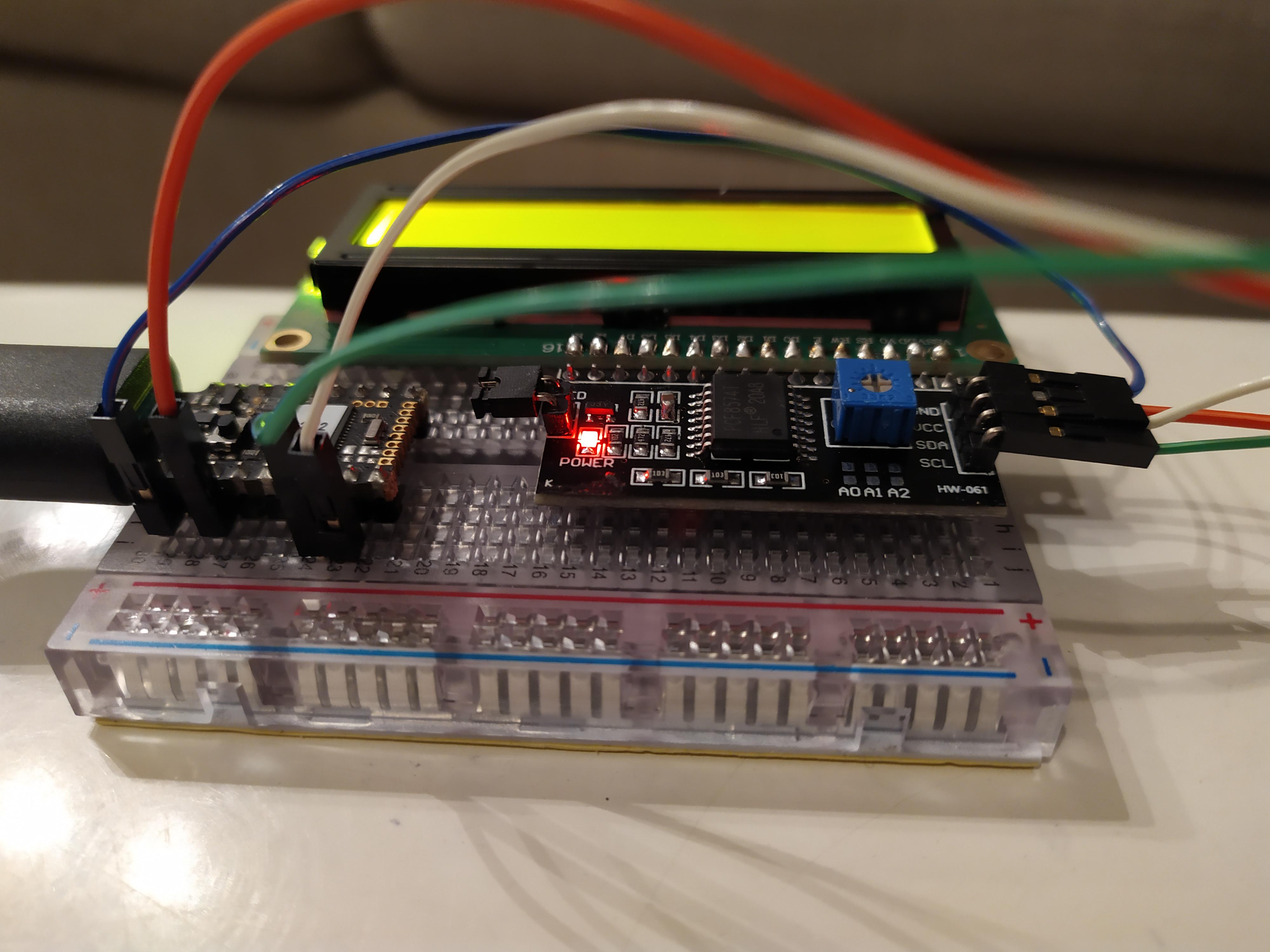
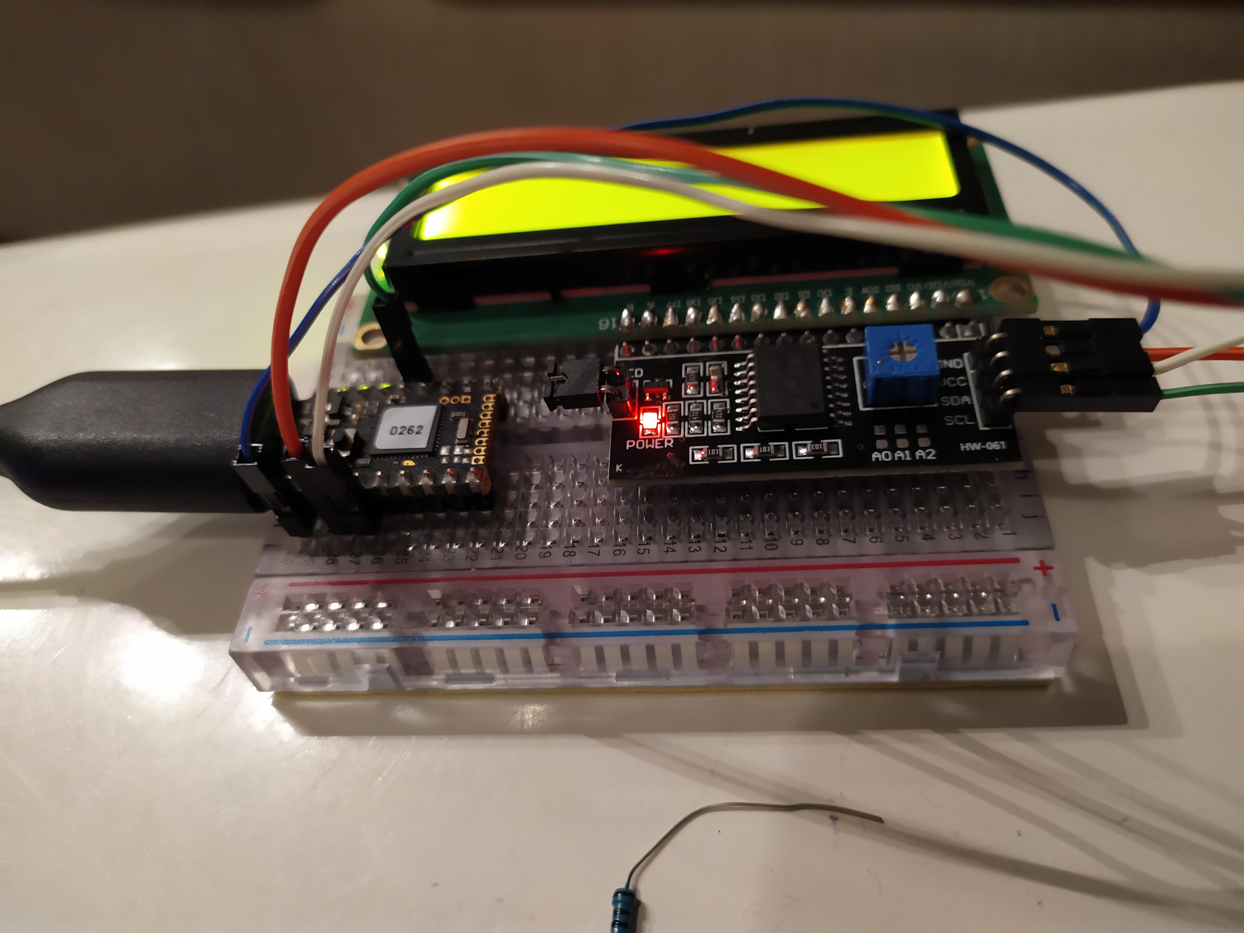
Hello,
I'm trying to connect a HD44780 LCD Display to a Pico but get the below error. I use two 4.7K resistors but maybe have connected them incorrectly (3.3-SDA,3.3-SCL)?
I'm using the native Web IDE on Windows 10.
Many thanks
2 Attachments