-
• #2
Hmm Bangle.JS is a DT NO1 F18 Outdoor-Sport Smartwatch from the shelf. Gordon has done many reverse engineering to make Espruino work on it. Browsing through the code you will find a lot details. The board file is a good starting point.
-
• #3
Hi! There's a page describing how everything is connected on the watch, including some shots of the PCB: https://www.espruino.com/Bangle.js+Technical
However as @MaBe says, because it's reverse engineered I don't have full schematics for it.
-
• #7
EDIT 2020.0719-1559
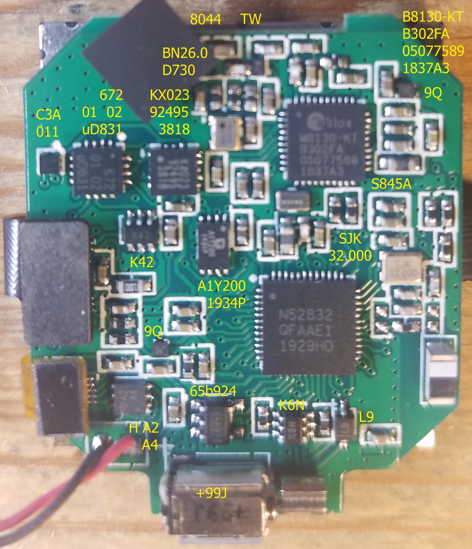
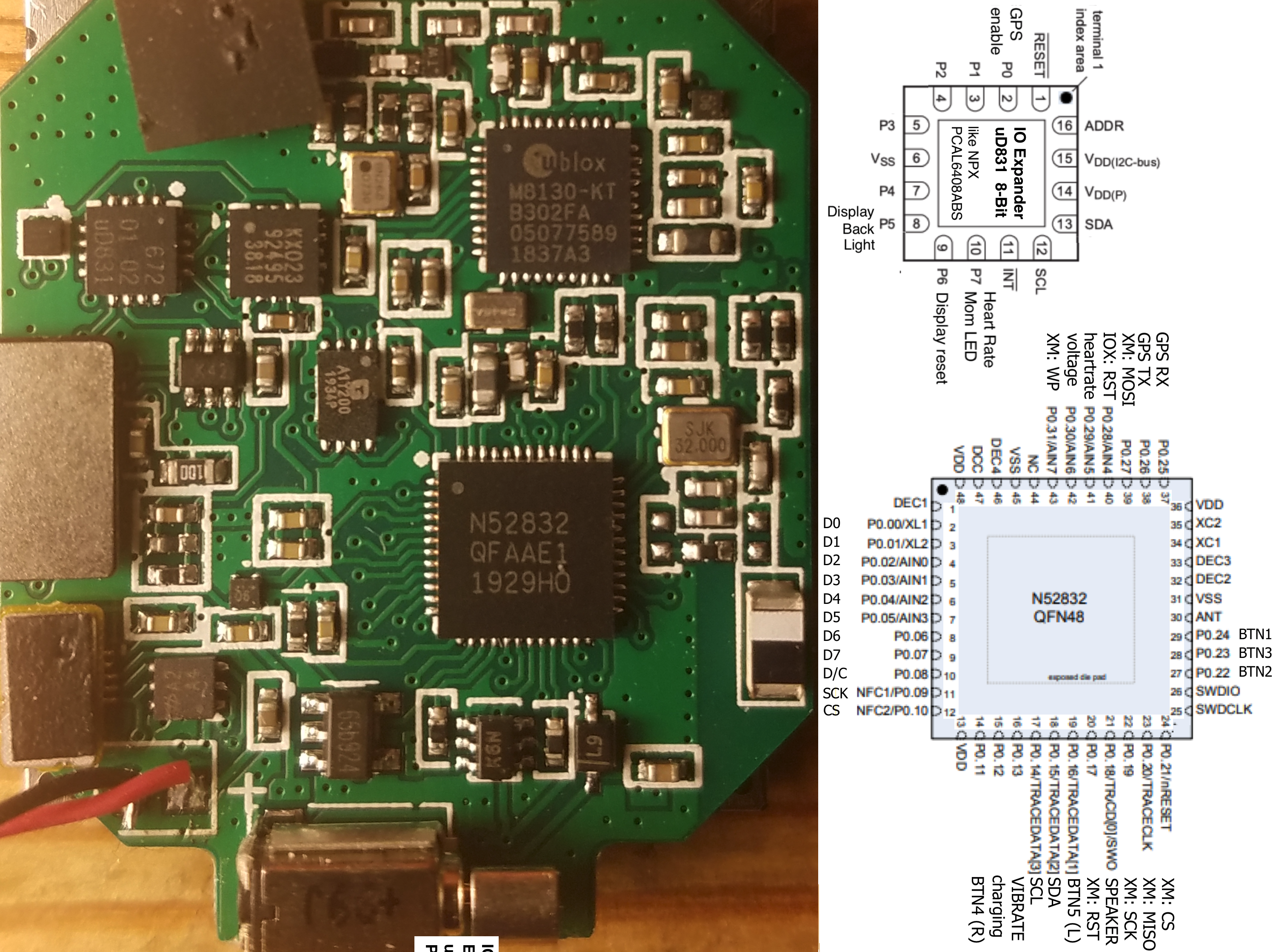
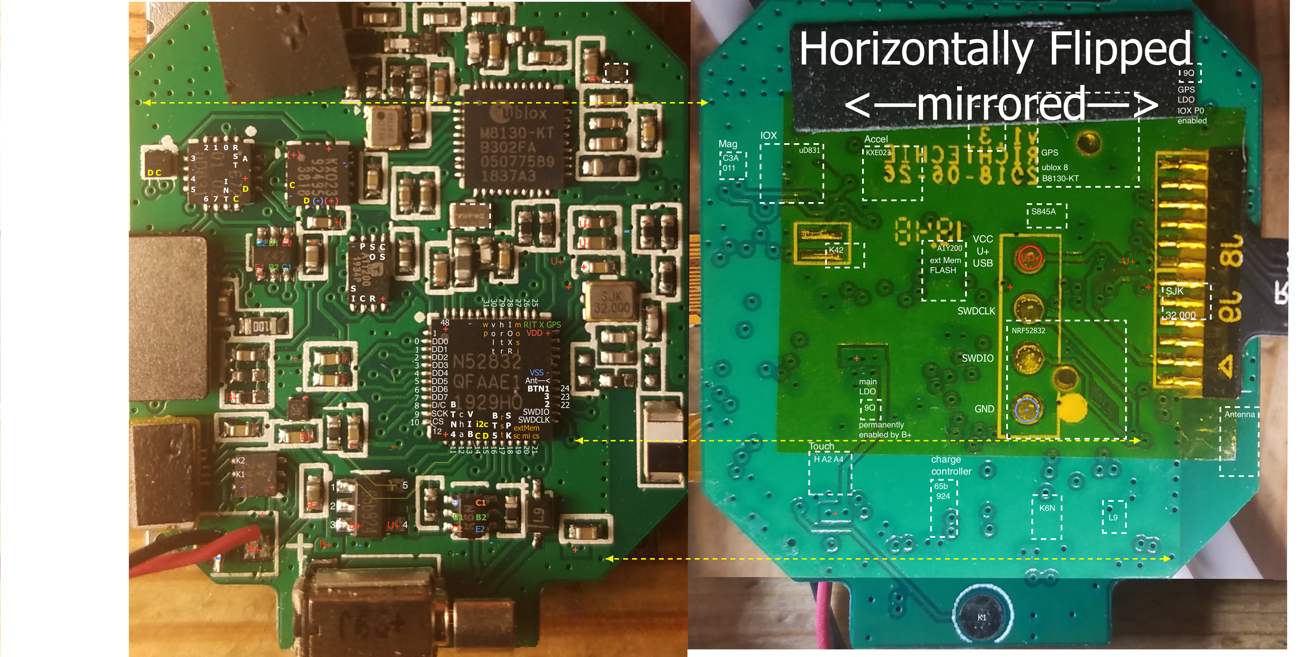
Some information from inspection and discovery on non-destructive tear-down I did quite a while ago (on a watch with piezo speaker). Note that the chip marked with 'Mag?' in the main shot on https://www.espruino.com/Bangle.js+Technical is the port expander. The Mag(netometer sensor) is the very small chip to its left with very few connections. Zoom into some of the pics, especially the one with the mirrored back, in which I marked some traces, mainly with + for Vcc, - for Ground, C for clock and D for data for the I2S. Port expander has still some unused extensions ;-) ... The first two pic shows IC identifications. The third one I used to follow the PCB traces on front and back. In any graphics editor take a line / dashed double arrow line and move it around to identify the same location on the front and back. I used that technique to follow the traces between the ICs as they go between front and back via the vias.
3 Attachments
-
• #8
EDIT 2020.0719-1559
List of ICs
counter clock wise starting with nrf52932 (name/id details may slightly vary between individual watches / production batches):
- nrf52832 - N52832 QFAAE1 1929HO
- xtal - SJK 32.000
- xtal? - S845A
- gps - ublox M8130-KT B302FA 05077589 1837A3
- gps iox P0 enabled (?) LDO 3.3V Regulator - 9Q|R (| date) like ON Semi's NCP161 XDFN4
- ? - TW
- ? - 8044
- xtal? - BN26.0 D730
- accelerator - KX023 92495 3818
- io expander - 672 01 02 uD831 (? NPX (ex Philips) PCAL6408A)
- magnetometer - C3A 011
- dual PNP bipolar transistors - K42 (? DIODES' ... MMDT3906)
- serial flash - A1Y2000 1934P
- main perm enabled (?) LDO 3.3V Regulator - 9Q|R (| date) like ON Semi's NCP161 XDFN4
- touch controller - Holtek H A2 A4 - 2 capacitive touch keys
- battery charge controller - 65b924
- vibr motor - +99J
- dual NPN bipolar transistor - K6N (DIODES' K6N MMDT3904)
- ? - L9
nrf52832 pins and purpose
counter clock wise starting Left top in shot with pin 1, then Bottom, Right, Top, with GPIO (in/out) and usage (from bangle board .py file https://github.com/espruino/Espruino/blob/master/boards/BANGLEJS.py and inspecting watch / non-destructive tear-down):
- L -
- L - GPIO D0 (o) - display D0 - 8-bit parallel mode ST7789 controller
- L - GPIO D1 (0) - display D1
- L - GPIO D2 (0) - display D2
- L - GPIO D3 (0) - display D3
- L - GPIO D4 (0) - display D4
- L - GPIO D5 (0) - display D5
- L - GPIO D6 (0) - display D6
- L - GPIO D7 (0) - display D7
- L - GPIO D8 (o) - display D/C - display data/command
- L - GPIO D9 (o) - display SCK - display serial clock
- L - GPIO D10 (o) - display CS - display chip select
- B - VDD - + Vdd
- B - GPIO11 D (i) - BTN4 - Button 4 - touch left area from touch controller
- B - GPIO12 D (i) - cha - charge controller status (neg charging)
- B - GPIO D13 (o) - VIB - Vibration Motor via R and 1st transistor in K6N dual array
- B - GPIO D14 (o) - i2c C - i2c clock (to accel, io expander, magn)
- B - GPIO D15 (i/o) - i2c D - i2c data (to/from accel, io expander, magn)
- B - GPIO D16 (i) - BTN5 - Button 5 - touch right area from touch controller
- B - GPIO D17 (o|i) - extMem rst - reset to external flash memory | qio: D3
- B - GPIO D18 (o) - SPKR - Speaker via R and 2nd transistor in K6N dual array
- B - GPIO D19 (o) - extMem sc - sck serial clock to external flash memory
- B - GPIO D20 (i) - extMem mi - master-in/slave out from external flash memory | qio: D1
- B - GPIO D21 (o) - extMem cs - chip select to external flash memory
- R - SWDCLK (i) - SWDCLK -on pad on back of main board for pogo pin
- R -SWDIO (i/o) - SWDIO - on pad on back of main board for pogo pin
- R - GPIO D22 (i) - BTN2 - Button 2 - push button (middle when right facing)
- R - GPIO D23 (i) - BTN3 - Button 3 - push button (bottom when right facing)
- R - GPIO D24 (i) - BTN1 - Button 1- push button (top when right facing)
- R - Ant - Antenna BLE
- R -VSS - - Vss
- R -
- R -
- R -
- R -
- R - VDD - + Vdd
- T - GPIO D25 (o) - GPS TX - serial transmit to gps RX
- T - GPIO D26 (i) - GPS RX - serial receive from gps TX
- T - GPIO D27 (o|i) - extMem mosi - matser-out/slave-in to ext flash memory | qio: D0
- T - GPIO D28 (o) - IOXR - IO eXpander Reset - io expander / portexpander reset
- T - GPIO D29 (i) - hrtr - heart rate (analog value) from heart rate monitor, analog input
- T - GPIO D30 (i) - volt - battery voltage from R voltage divider, analog input
- T - GPIO D31 (o|i) - wp - extMem wp - write protect to external flash memory | qio: D2
- T -
- T - VSS - - Vss
- T -
- T -
- T - VCC - + Vdd
uD831 IO Expander / Portexpander
The way it is wired up it looks like a NPX (ex Philips) PCAL6408A: Low-voltage translating, 8-bit I²C-bus/SMBus I/O expander. neg_INT pin as well as port P1..P4 pins 3..5 and 7 seem not to be connected and configuration / initialization state is 'Power-Up default' / reset default.
Address of IO Expander / Portexpander on I2S bus is 0x20- A(ddress) pin 16 input line grounded.
PortsBits (and pins) of IO Expander / Portexpander purpose and mask (according to wiring, bangle board .py file https://github.com/espruino/Espruino/blob/master/boards/BANGLEJS.py and .c code file https://github.com/espruino/Espruino/blob/master/libs/banglejs/jswrap_bangle.c ):
- P0 (2) - pin_en - GPS enable - IOEXP_GPS 0x01 via GPS LDO 9Q|R enable pin
- P1 (3) - ? NC
- P2 (4) - ? NC
- P3 (5) - ? NC
- P4 (7) - ? NC
- P5 (8) - pin_bl - Display Back Light - IOEXP_LCD_BACKLIGHT 0x20 via TR2 PNP Array K42
- P6 (9) - pin_rst - Display Reset - IOEXP_LCD_RESET 0x40
- P7 (10) - pin_led - Heart Rate Monitor LED - IOEXP_HRM 0x80 via TR1 PNP Array K42
Espruino Bangle.ioWr(<portMask>,<onOffInversedBoolean>):
Bangle.ioWr(0x20,false)or...,0)turns display back light on (when display is on)
-Bangle.ioWr(0x20,true )or...,1)turns display back light off (when display is on)
-Bangle.ioWr(0x80,false)or...,0)turns heart rate monitor LED on
-Bangle.ioWr(0x80,true )or...,1)turns heart rate monitor LED off
- nrf52832 - N52832 QFAAE1 1929HO
-
• #10
@allObjects I guess this information is completely sufficient. Thanks a lot.
-
• #11
Wow, thank you! I'll have to see about adding that to the Bangle.js technical page - thanks for the note about magnetometer/IO expander too - that makes a lot more sense :)
-
• #12
Updated / complemented posts #7 and #8 (Edit 2020.0715-2140).
@Gordon, Bangle board .py file https://github.com/espruino/Espruino/blob/master/boards/BANGLEJS.py includes incomplete/contradicting information in comments for the IO Extender Port assignments / usage. Working a second time thru the main board shows that he pin_led for the Heart Rate Monitor LED goes thru the K42 driver - makes more sense than my initial display based on the board file. (Btw, it would be nice to have also an .ioRd() like the .ioWr() to easily access the IO Expander. I tried to do with I2C1, but got varying values return that were inconclusive).
-
• #13
Thanks - just updated the comments (I think I was numbering some starting from 0 and some starting from 1!).
it would be nice to have also an .ioRd() like the .ioWr()
I don't believe the expander can be read from at all? There is actually an internal variable in Espruino containing the state of everything on the expander that I guess could be exposed, but I think its use is pretty limited.
-
• #14
Will look for this variable... because most certainly it is/has to be synced when using
Bangle.ioWr(). -
• #15
Updated / complemented posts #7 and #8 (EDIT 2020.0719-1559):
- Capacitive Touch device on the display - transparent film on top of glass of display - is definitely a 2 key circuitry and is connected to the 2-key Holtek H A2 A4 capacitive touch controller (4 key would have been really nice and better product design decision (There is similar controller for that available that for sure could have been made to fit. There are still 4 ports unused on the interrupt capable I2C connected IO Extender. Using them and the interrupt would have even saved a pin on the NRF52832).
- K6N and K42 are dual NPN and PNP transistor arrays that drive the Vibration Motor, Speaker, Heart Rate Monitor LED, and Back Light of the display (and L9 is the revers / protection diode against transients from the vibration motor).
- Q9|R9 are LDO 3.3Volt Voltage Regulators, one is IOX P0 enabled for enabling/powering GPS, and the other one is permanently enabled as the main LDO Regulator powering 'the rest'.
- 65b924 LIPO single cell charge controller mast have a built-in polarity protection because I cannot find the usual diode for that else where on the main or flex board.
- Power markers + (max 3.3V), B+ (up to 4.2V) and U+ (5V USB) added for distinction of the different power 'rails'. With charge controller having built in polarity protect, U+ is actually U- USB -5V when charge cable is connected 'the reverse/wrong way'. Did not test that but have not heard any complaints about fried watches nor fried myself one even though I cannot absolutely deny having ever connected the other way...
- Resistors and capacitor network - white box with 2 resistors and one capacitor right next to the right bottom corner of display connector - is the voltage divider to measure the battery voltage. Measured +4.18V B+ and +1.950V at divider point. Measuring - powered off but still in circuit - 996K and 930K. Calculated divider point voltage would be about +2.0183V - a difference of 68mV... a 3.5% error... acceptable. Will see what BangleJS measures...
- Capacitive Touch device on the display - transparent film on top of glass of display - is definitely a 2 key circuitry and is connected to the 2-key Holtek H A2 A4 capacitive touch controller (4 key would have been really nice and better product design decision (There is similar controller for that available that for sure could have been made to fit. There are still 4 ports unused on the interrupt capable I2C connected IO Extender. Using them and the interrupt would have even saved a pin on the NRF52832).
-
• #16
Wow, that's great - thanks! And I can confirm, I've tried connecting power the wrong way and it doesn't destroy anything :)
-
• #17
Detail about KN6 (NPN) and K42 (PNP) transistor arrrays:
KN6 (NPN) transistor array bases for vibration motor and speaker are driven via current limiting resistors. K42 (pnp) transistor array bases for display back light and heart rate monitoring LED are directly driven by the IO expander port pins and have most likely an integrated resistor to limit base current and with that limiting the load on the IO extender output ports (pins) P5 (8) and P7 (10).
Typical of driver transistor arrays is the Base-Emitter resistor to shut the transistor on floating base. It is possible that both KN6 and K42 contain such resistors.
Details about pull-up resistors on buttons 1 thru 3:
The three (3) resistors in upside-down of uppercase L layout 'above' the antenna / to the right and above the SJK 32.000 Xtal on the black flex cable connection side are pull-up resistors for the physical push buttons BTN1, BTN2 and BTN3. Their value is so high that touching the hot end with the probe of the multi-meter for measuring the voltage has the same effect as briefly pushing the related button.
 MaBe
MaBe Gordon
 user115072
 jcmb
jcmb allObjects


Bangle is absolutely amazing product, Just wanted to know if i can get the hardware/Schematics reference files for the same. If yes where ?
Thanks in advance for all the replies