-
• #2
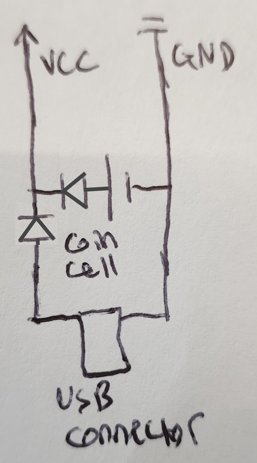
...not really... you will destroy your button cell... but something like below will work:
1 Attachment
-
• #3
Thanks, and nice editing!
Is that diode all I need for a completely safe circuit? Is the diode a specific value/kind? I have little to no experience with non-LED diodes, so I need a little help here. Thanks. -
• #4
Lowest forward bias is best... a good schottky does well. And yes, this is perfect protection. You have just to know that your module has
3 - diodeForwardVoltageas input voltage (less than 3V). -
• #5
You have just to know that your module has 3 - diodeForwardVoltage as input voltage (less than 3V).
Sorry, but can you clarify that in layman's terms for me please?
-
• #6
Diodes have a behavior like this: you run them in reverse, they block. Your run them in forward mode, they let the power pass but
take a tollof it. The toll is 0.2...0.8, depending on the circumstances (SEE https://learn.sparkfun.com/tutorials/diodes/real-diode-characteristics). To protect also your button cell from powering the USB, we need a 2nd diode:
1 Attachment
-
• #7
Are you talking about the MDBT42 breakout rather than a bare module? https://www.espruino.com/MDBT42Q
Just checking since the breakout will be fine off 5v as it has a regulator (as long as you use the Vin pin, not 3.3v!) https://www.espruino.com/MDBT42Q#pinout, but the module won't be, since it'll take only 3.6v maximum.
But as @allObjects says you just need some diodes in there. I'm not sure he was totally explicit about this but Schottky diodes are best for what you want since they lose smaller amounts of voltage (~0.3v vs ~0.7v for normal diodes) - while that doesn't matter for USB, the less voltage you can lose from the coin cell the better as it means more battery life.
-
• #8
Hey @Gordon and @allObjects,
I just tried this out on a breadboard, and while it does work, my LEDs (multiplexed 7 segments) are very dim when powered by the coin cell only. Without the diode between the coin cell and the microcontroller the LEDs are nice and bright. I have 5 other LEDs each wired to an IO pin and they are slightly dimmer too. When powered by USB though they all light up perfectly.I bought 1N4007 diodes, the shop didn't have any schottky diodes. Will the LEDs be fine if I use a schottky diode? Thanks.
-
• #9
With a regular diode like 1N4007, you have about 0.6-0.7V voltage drop. So with a 3V coin cell you have ~2.3V for the LEDs, with a schottky you would have ~2.7V.
It will be better with a schottky, but several LEDs can be a pretty heavy load for a coin cell...What color LEDs do you have? (forward voltage depends on color). Do you have any current limiting resistors for the LEDs? Maybe you can can change the current limiting resistors to lower value ones. But do the maths, so you don't burn the LEDs if you power it from 3.3v
Or just remember to only power your board from 3V source (just use 2*AA batteries if you don't have a variable power supply) -
• #10
The diodes are a simple hack.
The proper way would be a hot swap controller, e.g. LTC4227 (check the datasheet for allowed voltages and and current consumption). It senses the input voltages of multiples sources and controls a transistor to connect the source with the highest input voltage to the output. -
• #11
A Schottky diode would be better, but it may not be good enough.
The differences in brightness are what you'd expect given the different voltages I'm afraid. If you're not tied to using a coin cell then you could instead use a LiPo battery - those supply 3.7v(ish) and would provide enough voltage to keep 3.3v on the microcontroller most of the time - plus they are rechargeable :)
As @maze1980 points out, the diodes aren't the best way to do things, but they are easy! Another thing I do with the Original and Pico boards is the circuit shown here: https://www.espruino.com/Original#power
Looks compilicated but you only care about the left-hand half. Basically you use a diode for USB where you have enough voltage to spare, and then you use a PFET (a p-channel field effect transistor) across the battery that is controlled from USB power. That way when there's no USB power the battery is used, and when there is, the battery is disconnected and everything is powered through the diode.
-
• #12
Hey @AkosLukacs, I have two multiplexed 7-segment LEDs and five more LEDs each with their own GPIO pin, all colored blue. All of them are tied to a 330 ohm resistor in series. The microcontroller I'm using operates on 3.3v logic so this might not be necessary, I just tossed the resistors in for safety. The LEDs are fairly visible during normal use, although not at their peak brightness. My circuit is a wristwatch, so I don't have the real estate for two AA batteries.
-
• #13
Ah, ok. I meant the 2*AA suggestion while you are developing, so you don't waste a lot of coin cells. Blue LEDs forward voltage is right around 3V or so,
Gordon's circuit maybe the easiest way forward, as there is no diode waste running from the battery. And no different voltage levels when powered from USB or battery. -
• #14
Yeah, so with blue LEDs you don't have much voltage in hand. Even with the 3v from the coin cell it's going to be a bit tight (but the good news is it'd so 'on edge' that moving to a schottky will help you out noticeably).
Personally, what I'd suggest is to use a small LiPo rechargeable battery and a LiPo charger board (which will have a USB connector on it anyway). You can then power the watch direct from the LiPo, and when you plug into USB it'll charge the LiPo which will have the effect of also powering the watch.
With a bit of searching local shops or eBay/Amazon you may even find a cheap mini torch/power bank that has a LiPo battery, charger and USB connector in it that you could use for parts.
 allObjects
 BootySnorkeler
 Gordon
 AkosLukacs
 maze1980
Hey what's up,
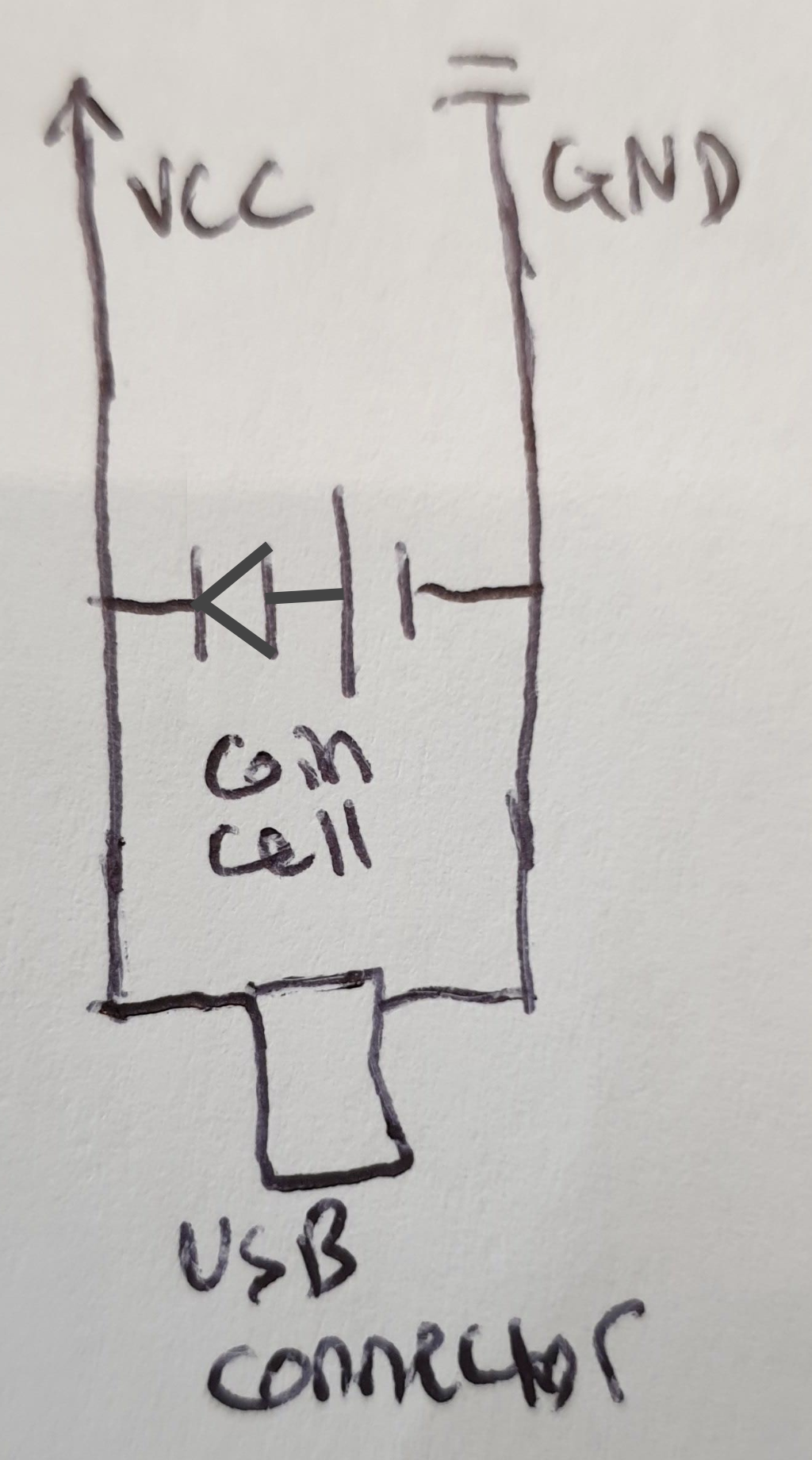
Will I hurt my MDBT42Q module by connecting a coin cell battery in parallel with a USB jack(or any other connector really, like a JST) for optional external power? Will it hurt the battery? I've attached a simple diagram to further clarify what I mean.
The coin cell is a 3V CR1225 cell and the external power connector will be a similar 3.3v power source.
EDIT: the external power connector will also handle data transfer through the RX/TX lines.
1 Attachment