-
• #3
Thanks! Unfortunately I wasn't allowed to share any information about this until they were given out to the conference attendees, but they're really exciting. There was a great response at the conference.
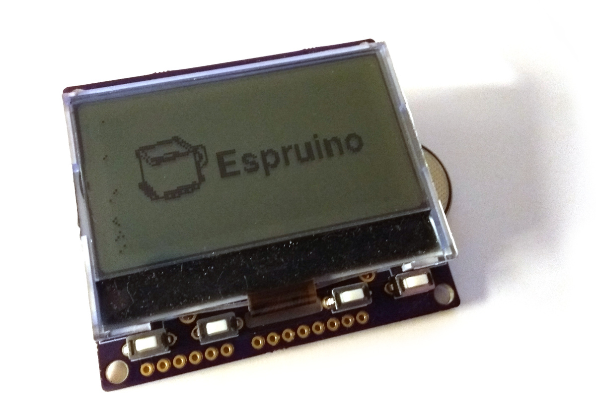
These are the fabled 'Bluetooth Badges' that are going out to Patreon $20+ supporters as well (with a custom Patreon PCB).
If anyone else is after these, everything is Open Source (as usual!) so you could make them yourself (although the FPC connector is 0.5mm pitch so is pretty painful to solder!) : https://github.com/nearform/nceubadge
The response has been so good I'm in the process of making a new, proper Espruino device with an LCD that should be available for sale at some point early next year - it'll be set up as a smart display, but arranged so that you can clip it onto something to use as a badge if you want to!
-
• #4
@Gorden, is power consumption of this new Espruino device the reason to select LCD over OLED?
-
• #5
So nobody learned anything at NodeConf - too busy playing with their badges? I would have been. Very nice.
-
• #6
@allObjects - yes. And size. It's hard to get affordable yet big OLED displays. Even the small 128x64 OLEDs use around 20mA when on - so that's 10 hours on a CR2032. The LCD uses 0.15mA, so it's plenty for a week of usage.
@Ollie there was definitely quite a lot of tinkering by some people. If you looked from the back of the conference hall you could usually see the Web IDE open on a few people's computers :)
-
• #8
@Gordon, I like the fact that the LCD used is SPI connected. I hope that on the new device the pins that are used to drive the LCD's MOSI, CD and NRES are still brought out (onto the headers)...
Btw, I finally got access to a micro:bit from a local electronics store. First I was a bit disappointed about how to access the extra pins other than 0, 1, 2, 3.3 and GND. But then I came across and Edge-Connector on a breakout board. Could such an approach also be viable for the new device? I know that extra costs are a challenge...
-
• #9
I hope that on the new device the pins that are used to drive the LCD's MOSI, CD and NRES are still brought out
Really? there are loads of GPIOs available on the chip - wouldn't it be confusing if a few extra pins were brought out that went up and down every time you accessed the LCD?
but then I came across and Edge-Connector on a breakout board
Getting those connectors cheaply is a pain - it only works because micro:bit was sold in such high volumes... I really wanted to do something like that with some of the other boards like the Pico but just couldn't find the connectors :(
As it goes, I'll probably end up using Arduino pinout I think - it fits really well around the LCD itself, and there are loads of super-cheap boards and getting started kits for it.
-
• #10
MOSI/MISO/CD/RES can be shared in a SPI bus, just not CS - that was the thought behind my comment. But if you think there is plenty of other pins to populate the Arduino pinout, no need to share.
-
• #11
Yes, it works out just about perfect - there are enough for a full Arduino Uno pinout, plus one left for the backlight :)
-
• #12
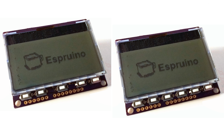
This is the kind of thing I'm looking at...
1 Attachment
-
• #13
Looks pretty cool. I like the 'keyboard'. I would prefer to also have an Enter: a 5th button in the center (4 way button/control with Enter). I notice though the conflict with the LCD connector... 3 and 3 buttons are a space issue... Moving the LCD a tiny bit up? If not possible: turning the LCD around and have the connection on the opposite site? Can 'survive' that the 'porch' - space between display and keys - gets lost... Space could then even provide 6 buttons: 4 way plus A and B, and A and B pressed together is Enter... or Enter and Esc... what ever... Having the display close to the buttons makes sense for dynamic button labeling...
Badly photoshopped it looks like this...
1 Attachment
-
• #14
Wow, that's actually some pretty convincing photoshopping :)
The buttons are there precisely because there's space needed for the ribbon cable from the LCD, and I thought I could fill the gap on either side with something. Because I'm using the Arduino footprint I don't have space to move the LCD up (or flip it around) either, so I don't think there's really a way around having a gap there (I also don't have any spare IOs!).
I probably won't actually pre-install the buttons (because of the cost involved in doing a two-sided board) and would just put two sideways facing buttons on the back of the board - but at least they're there if anyone wants them.
What are everyone's thoughts about pre-installing the Arduino headers? It makes the whole thing more plug and play and beginner friendly, but adds to the cost and makes the whole device thicker than it would otherwise have been.
 allObjects
 Gordon
 Ollie
Ollie tbd
tbd

Nodeconf badge by @Gordon
a lovely badge that allows exploration of the Espruino platform
page: http://nodeconfeubadge.org/
hardware: https://github.com/nearform/nceubadge/tree/master/hardware
short video: https://www.youtube.com/watch?v=xAry2SLZ51I
LATER EDIT:
@Gordon presentation - https://m.youtube.com/watch?list=PL0CdgOSSGlBaxNkrUIHrhd1f3ch45f66_&v=y9vySsTnp8M