-
• #2
Yes, it should work fine. All you really need are the magic initialisation codes, which seem to be covered here and here - then you can base it on another similar LCD driver's code like this one
Try pasting this into the Web IDE:
var exports={}; exports.connect = function(/*=SPI*/_spi, /*=PIN*/_dc, /*=PIN*/_ce, /*=PIN*/_rst, callback) { var LCD = Graphics.createArrayBuffer(128,64,1,{vertical_byte:true}); var spi = _spi; var dc = _dc; var ce = _ce; var rst = _rst; setTimeout(function() { digitalWrite(dc,0); // cmd digitalPulse(rst, 0, 10); // pulse reset low setTimeout(function() { spi.write([ 0xA2, //set the LCD bias to 1/9th 0xA0, //horizontally "normal" (not flipped) 0xC8, //vertically "flipped" (complements the command above) 0x23, //the internal resistor divider set to 3 (from 0..7) 0x2F, //power control, all internal blocks ON 0x81, //enter dynamic contrast mode 31, // Data for the dynamic contrast mode, set to 31 (from 0..63) 0x40, //go back to the top left of the display ], ce); if (callback!==undefined) callback(); }, 100); }, 100); LCD.flip = function () { for (var y=0;y<8;y++) { digitalWrite(dc,0); // cmd spi.write([0xB0|y/* page */,0x00/* col lower*/,0x10/* col upper*/],ce); digitalWrite(dc,1); // data spi.write(new Uint8Array(this.buffer, 128*y, 128), ce); } }; return LCD; }; // or whatever your pins are: SPI1.setup({ sck:B3, mosi:B5 }); var g = exports.connect(SPI1,B6,B7,B8, function() { g.clear(); g.drawString("Hello",0,0); g.drawLine(0,10,84,10); g.flip(); }); -
• #3
Hmm, I can't get this to work. In their init code for u8glib they use different values for setting the LCD bias etc...
Also this display is 132*64 not 128*64
-
• #4
Hi, Ducky. I'm glad to hear you're using the Pax Instruments LCD. This is the first I've heard of the Espruino, so I'll do my best to help.
Can you get anything on the display using the st7565.c ? In u8glib the st7565 driver works well enough to get an image on the display, but the pixels are a bit off because the LCD is 132 and not the 128 pixels the driver was expecting.
Have you used the LCD with an Arduino and verified that it does work?
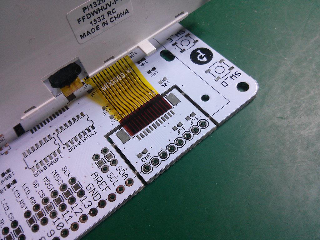
Are the wires connected correctly? The LCD plugs into the connector the same orientation as on the shield, which is not necessarily intuitive. See the attached image for orientation.
1 Attachment
-
• #5
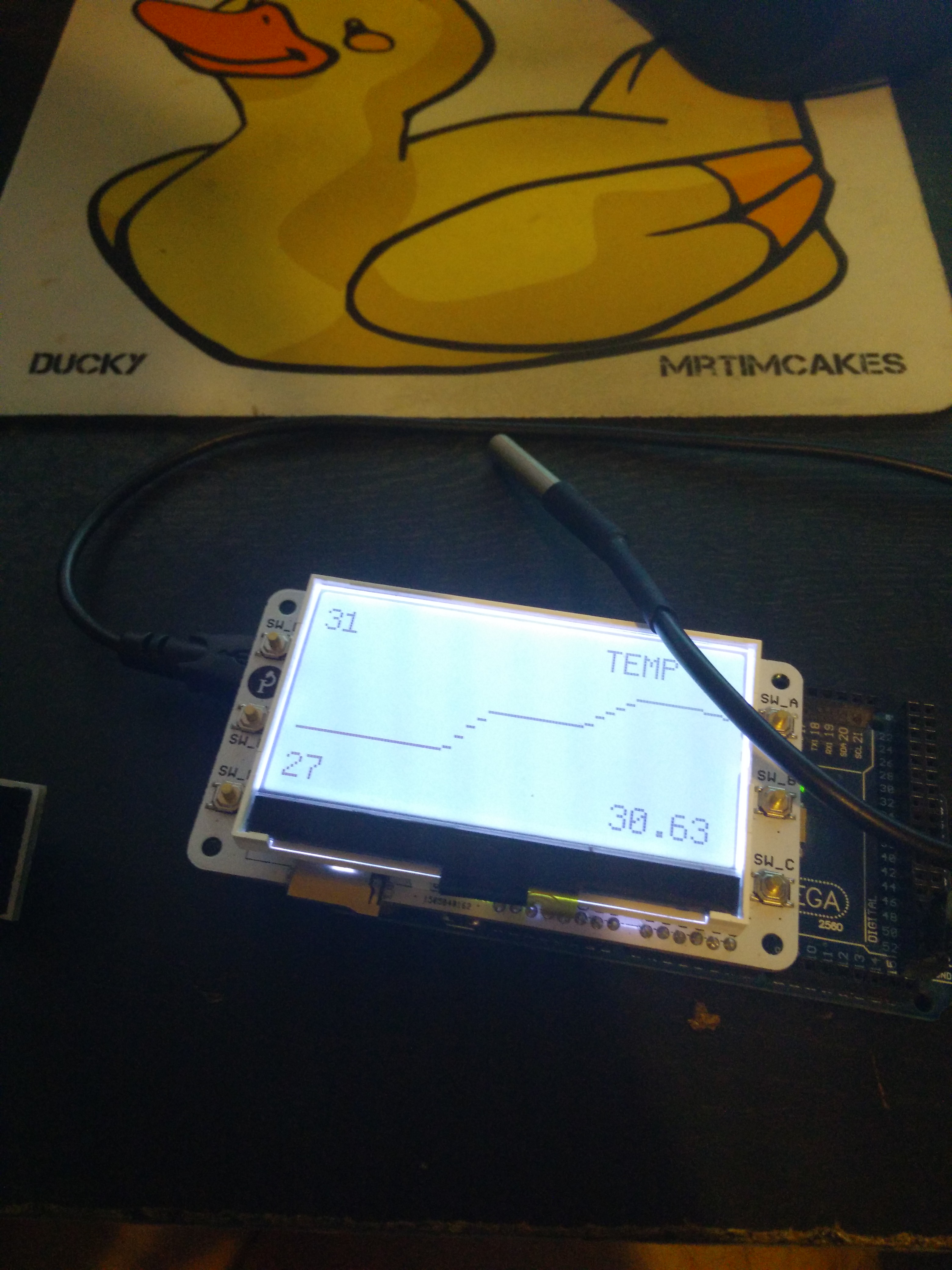
The connections are correct (Tried reconnecting a few times) and the connector is in the right orientation (I can control the backlight). And i can get things to display with an Arduino (Even on a mega with different pins), I even made a nice Temperature grapher with a DS18B20. But I'd love to program it with Espruino its just funner in JavaScript.
1 Attachment
-
• #6
Maybe just try copying the init code that works on arduino?
I don't have a display here so can't do any debugging for you
-
• #7
Taking Gordon's code as a template, I suppose it would look something like the code below. I pulled the init sequence from u8g_dev_st7567_pi13264.c and the define statements from u8g.h.
NOTE: The code block rendering engine turns hash marks into links. In the define statements below you'll have to remove all the forward slashes.
// I grabbed these define statements from u8g.h in the u8glib library // using this command "grep -ir U8G_ESC_* utility/u8g.h" \#define U8G_ESC_DLY(x) 255, ((x) & 0x7f) \#define U8G_ESC_CS(x) 255, (0xd0 | ((x)&0x0f)) \#define U8G_ESC_ADR(x) 255, (0xe0 | ((x)&0x0f)) \#define U8G_ESC_RST(x) 255, (0xc0 | ((x)&0x0f)) \#define U8G_ESC_VCC(x) 255, (0xbe | ((x)&0x01)) \#define U8G_ESC_END 255, 254 \#define U8G_ESC_255 255, 255 var exports={}; exports.connect = function(/*=SPI*/_spi, /*=PIN*/_dc, /*=PIN*/_ce, /*=PIN*/_rst, callback) { var LCD = Graphics.createArrayBuffer(128,64,1,{vertical_byte:true}); var spi = _spi; var dc = _dc; var ce = _ce; var rst = _rst; setTimeout(function() { digitalWrite(dc,0); // cmd digitalPulse(rst, 0, 10); // pulse reset low setTimeout(function() { spi.write([ U8G_ESC_CS(0), /* disable chip */ U8G_ESC_ADR(0), /* instruction mode */ U8G_ESC_CS(1), /* enable chip */ U8G_ESC_RST(15), /* do reset low pulse with (15*16)+2 milliseconds (=maximum delay)*/ 0x0a3, /* 0x0a3: LCD bias 1/9 (suggested for the pi13264) */ 0x0a1, /* 0x0a1: ADC set to reverse (suggested for the pi13264) */ 0x0c0, /* common output mode: set scan direction normal operation/SHL Select, 0x0c0 --> SHL = 0, normal, 0x0c8 --> SHL = 1 */ 0x040, /* set display start line */ 0x028 | 0x04, /* power control: turn on voltage converter */ U8G_ESC_DLY(50), /* delay 50 ms */ 0x028 | 0x06, /* power control: turn on voltage regulator */ U8G_ESC_DLY(50), /* delay 50 ms */ 0x028 | 0x07, /* power control: turn on voltage follower */ U8G_ESC_DLY(50), /* delay 50 ms */ 0x026, /* set V0 voltage resistor ratio to 6 */ 0x0a6, /* display normal, bit val 0: LCD pixel off. */ 0x0C0, /* set contrast */ 0x018, /* contrast value*/ /*0x0ac,*/ /* indicator */ /*0x000,*/ /* disable */ 0x0af, /* display on */ U8G_ESC_DLY(100), /* delay 100 ms */ 0x0a5, /* display all points, ST7565 */ U8G_ESC_DLY(100), /* delay 100 ms */ U8G_ESC_DLY(100), /* delay 100 ms */ 0x0a4, /* normal display */ U8G_ESC_CS(0), /* disable chip */ U8G_ESC_END /* end of sequence */ ], ce); if (callback!==undefined) callback(); }, 100); }, 100); LCD.flip = function () { for (var y=0;y<8;y++) { digitalWrite(dc,0); // cmd spi.write([0xB0|y/* page */,0x00/* col lower*/,0x10/* col upper*/],ce); digitalWrite(dc,1); // data spi.write(new Uint8Array(this.buffer, 128*y, 128), ce); } }; return LCD; }; // or whatever your pins are: SPI1.setup({ sck:B3, mosi:B5 }); var g = exports.connect(SPI1,B6,B7,B8, function() { g.clear(); g.drawString("Hello",0,0); g.drawLine(0,10,84,10); g.flip(); }); -
• #9
Are the delays in the SPI commands necessary? Would I have to nest lots of setTimeouts?
-
• #10
I think probably you do need at least some of the delays, but it might be worth trying without.
Ahh, looking at that code again, it seems like those
U8G_ESC_DLY/etc macros are actually interpreted by another commandu8g_WriteEscSeqP. Rather then reimplementingu8g_WriteEscSeqP, it's probably easier to just unroll everything and nest timeouts where needed as you say. -
• #12
No sorry I didn't really try after this, been too busy.
-
• #13
There's now a module for this: http://www.espruino.com/ST7565
-
• #14
Would it be possible to add an optional parameter to the initialization to specify the resolution, then the PI13264 could be supported without a separate module?
-
• #15
Sounds like a plan - do you have one there that you can test with? I'd be interested to see if it works - maybe it's just missing the last 4 pixels, which I guess won't be a deal-breaker even as-is!
Personally I wonder whether I should actually do:
var g = require("ST7565").connect(spi, {rs:A7, cs:A5, rst:A6, width:132}, function() {
  g.clear();
});
For me, that's a lot easier to read and maintain than the unlabelled parameters.
-
• #16
Hmm, I can't get it to work at all, This display has a pin labeled A0, I'm assuming this is RS/DC for setting if it is Data or a Command.
As I don't have the middle pins soldered on I've changed the pins to
GND -> GND
VCC -> 3.3v
LCD_BL -> 3.3v
LCD_CS -> C5
LCD_RST -> C6
LCD_A0 -> C7
SCK - > B13
MOSI -> B15With this code:
var spi = new SPI();
spi.setup({ sck: B13, mosi: B15 });
var g = require("ST7565").connect(spi, C7 /* RS / DC */, C5 /* CS / CE */, C6 /* RST */, function() {
  g.clear();
  g.drawString("Hello",0,0);
  g.drawLine(0,10,84,10);
  g.flip();
});
That should work fine right?
-
• #17
Yes, that all looks fine - it should work!
Perhaps try:
g.setContrast(0.5, 7)and see if it goes black. It looks like different LCDs need wildly different drive voltages on them. -
• #18
Ooh, bingo should of tried that I did read it on the ST7565 page. Yeah just the last 4 width pixels are randomly lit. Excellent work on this module I couldn't wrap my head around that SPI init stuff.
Also g.setContrast(0.5, 6) is the sweet spot for this display.
 Gordon
 MrTimcakes
 user56610

 jonreid
Would it be possible to interface with the PI13264 from Pax Instrumets? The PI13264 is a ~3" (Actual pixels diagonally) 132*64 SPI LCD that uses the ST7567 controller. Its perfect to use as the Arduino Shield has a little snap-off piece that breaks out the already easy to use 1mm PCB connector (Which contains the backlight LED). On the Arduino they use a modified version of the u8glib graphics library, which when compaired to Espruino's graphics library is agony to write for.