-
• #2
Hi - sounds like a great idea!
Are you considering using one of the Bluetooth Espruino boards? Basically as long as you stop sending signals to the servo motor when you're not going anything, the power draw of the microcontroller should be pretty low as it'll just be asleep.
The difference between hardware/software timers won't really be an issue for you since when it's moving the servo will be drawing way more power than the microcontroller.
You can run those servos off a LiPo battery too - you won't get as much torque as if you ran them from the full 5-6v, but it should be enough.
I just checked with a FITEC micro servo here and it looks like when they're just sitting there not doing anything they draw about 3mA - so off a 2000mAh battery that's 670 hours -> about a month. I guess other servos (more expensive ones?) might draw less power though.
If you want to get it to work for longer off a battery you'll need to think about turning the servo motor on and off, so you only turn it on when you need to send a signal. If you do that hopefully you could get a year or more out of it.
The difference between the 3.3v voltage of the microcontroller and the ~4v voltage of the LiPo for the servo makes that slightly more painful to turn the servo on and off than it should be though. Normally you'd just use an FET to switch the GND wire, but you can't do that because it'd put 4v on one of Espruino's IO pins - instead you need to switch the power pin of the servo.
So you have a few options...
- The easy way is just to use a relay module (http://www.espruino.com/Relays) - but that's a bit big and clunky.
- You could use a MOSFET based solid state relay, like https://uk.farnell.com/vishay/vo14642at/relay-mosfet-spst-no-2a-60v-th/dp/2396108
- You can use a device called a 'High Side Driver' like this: https://uk.farnell.com/infineon/bsp452huma1/ic-smart-high-side-pwr-sw-sot223/dp/2215478 but it seems it can be hard to find ones that are big enough to solder nicely
- You could use a 'half bridge' motor driver (basically a high side driver plus a low side driver) - these are be more easily available on breakout boards, but might themselves draw some power when idle
- You could make your own 'high side' driver using two FETs and some resistors.
Hope that helps!
- The easy way is just to use a relay module (http://www.espruino.com/Relays) - but that's a bit big and clunky.
-
• #3
Thank you for this, it's super helpful.
Since this is the first time I'm trying this, I think I'll get the clunky relay module (and then upgrade once it works as expected).
Which is the cheapest board that could do this? I guess Pico is great cos it's tiny.
I ideally want to run a timer on the board and then at certain times, activate the servo.
To help save battery life, am I right in thinking I could switch the power pin of the servo (without blowing it)? Do you have any articles that explains this in more detail?
I've seen this which seem to show a super simple approach:
https://www.wilsonleite.net/espruino-servo/The adafruit site says "Never charge or use unattended.".
Is there a workaround for this, maybe safer batteries?
-
• #4
.
-
• #5
Brilliant application for getting into IoT... and very useful!
Espruino source/sink capabilities are not enough to power a servo directly, but they have plenty of power to drive the control line. You can go for a relay to switch the power of the servo, but a relay is a power hungry too. Simplest is to drive it with a FET - and it may even work to have the N-FET in the low side. Otherwise you need a P-FET. Depending on the battery you use and what protection circuitry is involved if needed at all, I see no reason why not have it 'unattended'. A PICO is fine if you tune the frequency when no clock crystal is on board. You may end up to connect it to a small display that would allow you to show and adjust the time as needed... Going Bluetooth / BLE - with the http://www.espruino.com/MDBT42Q breakout, you have communication and can control it from a phone... and get the temperature back... It all depends how elaborate you want to go... beginning w/ baby steps.
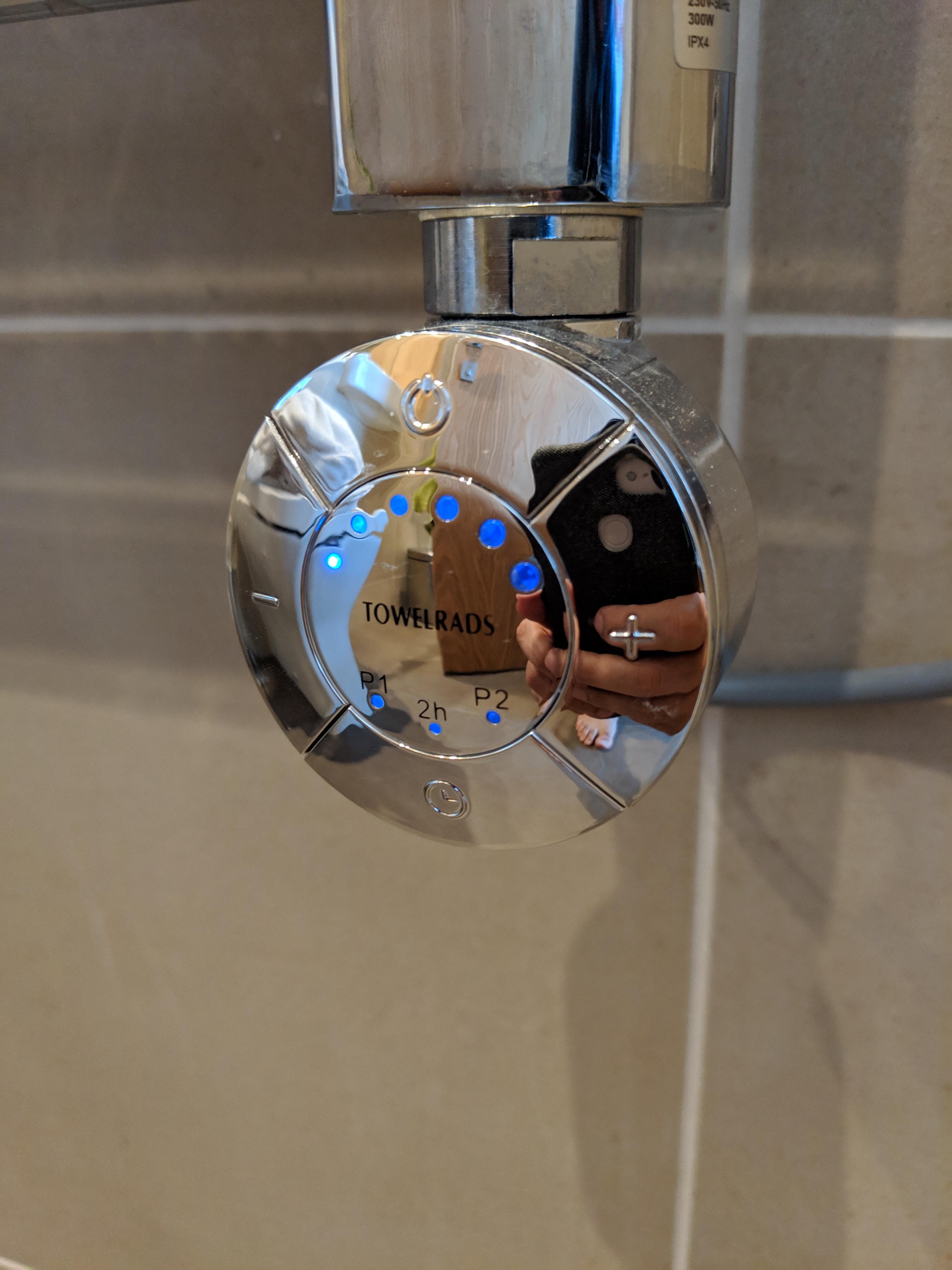
Do you know the force you need to do your switch? What is the stroke the switch has (if it is a push button switch)? Is the switch directly switching the towel rack heating element or just a control line?
Can you take and publish a pic of the switch?
-
• #6
Hey there,
I'm sorry, although I can code pretty well, all these terminologies are kinda lost on me. The pic of a button is attached, it doesn't require much force to push to be honest. I just need it to tap the power button at the top.
Is there a simple guide I can follow for the basics, something like this (but it's Arduino). They seem to use a hardware clock to limit the power draw of the servo which should increase the battery life.
Thanks!
1 Attachment
-
• #7
The product you are talking about is like that - http://www.towelrads.com/collections/electric/mccarthyelectric/ - with brochure at http://www.brittens-bathtime.com/wp-content/uploads/2017/04/Towelrads-2017-Brochure.pdf - w/ pages 101 / 102 show and describe the switch you took a pic of. ...pretty close to what I imagined.
In your picture I see gray power cored... if this goes to a wall outlet, you consider an alternative to the actual, physical pressing of a button: putting a box w/ Espruino and a 5V relay between the wall outlet and the radiator. You can then even integrate a 5V phone wall outlet power supply and never have to worry about power again. I used a pico to do my tests, but you may find the puck.js the better solution, because it has connectivity... and you need a driver N MOS FET anyway...
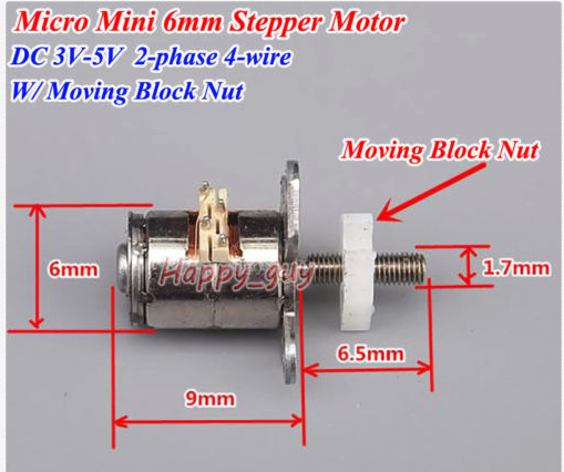
Btw, alternative to servo, a stepper w/ gear - see this post - or micro stepper with a lead screw for linear movement (pic attached) would do as well... and there are even more alternatives, food for future posts.
Took a look at the idea of driving a 9g micro/nano servo with 5 pins from a PICO. PICO as chip can handle a total of 120ma. Each pin can handle up to 25mA up to the combined total of the chip. With 5 pins I maxed out... Even though the pins could handle easily the 3.4mA standby power consumption of the servo and on move could provide the no-load of roughly 60..70 mA, the servo did not move: the voltage was too low: 2.7V something, which is typical for a loaded pin... and still way in the limit of 1 / HIGH output.
Resorting to a N MOS FET did the trick... put in the LOW side... When fed by USB through PICO's diode on vBat/USB puts the USB 5V down to 4.3V, still good enough . Connecting directly to rail up to 6V (4x1.5V... or 4x1.2V=4.8V w/ rechargeables) gives it a bit more umph. 1S LiPo may not be enough and 2S directly connected is probably too much, and it could also be an issue with PICO. a 5V bost converter w/ 1S and a bucket converter w/ 2S would do as well
Holding the servo to get an idea of the blocking current shows quite a draw, briefly over 200ma...
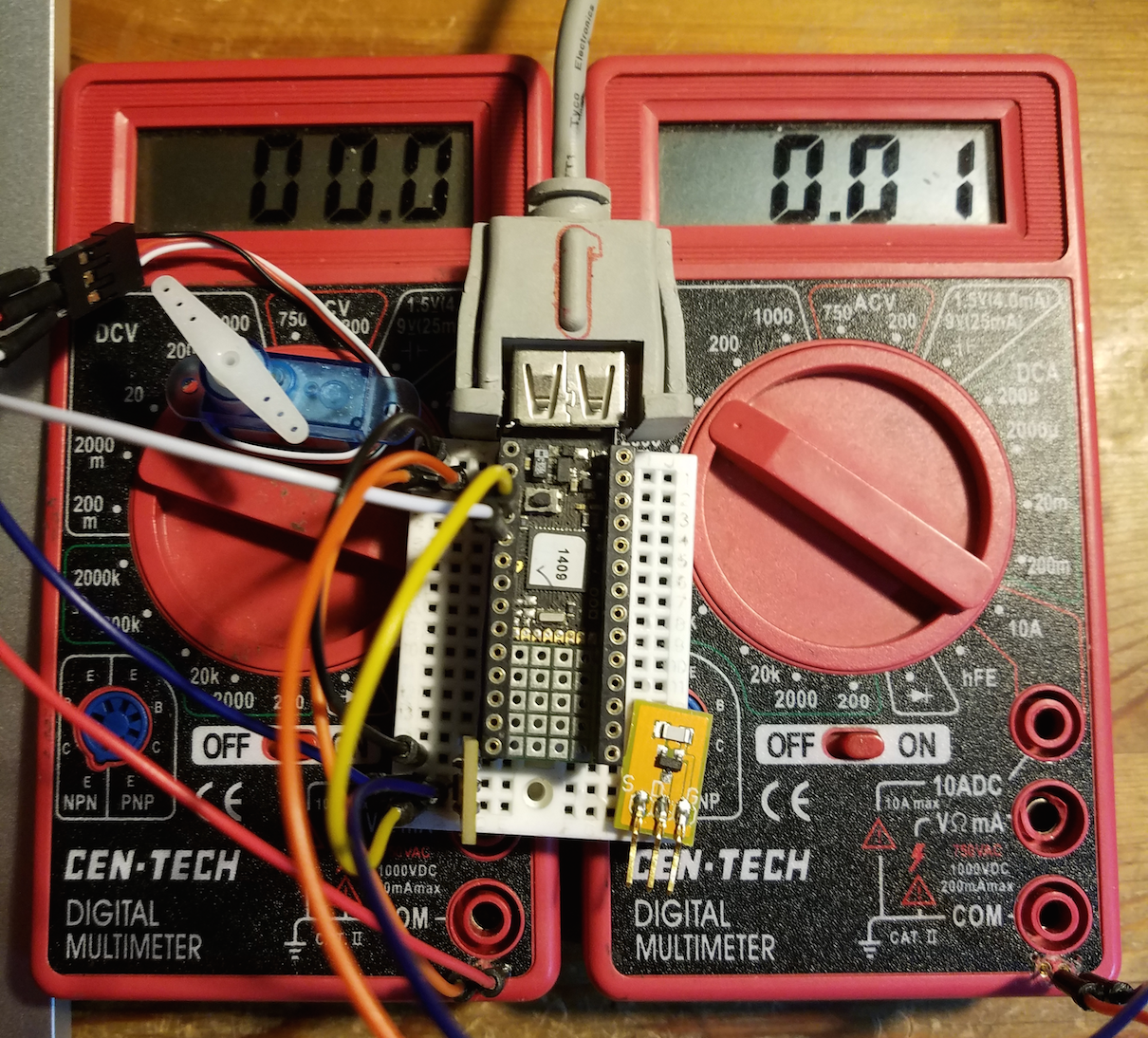
Attached is a still and a clip.
In clip it can be servo moves a bit odd: it goes very briefly in the wrong direction to then turn and to in the right direction to the desired position. Also weird is the start up... may be my servo is an out-layer...
The code was quite interesting to write, since all is timed. I added a command fifo in the logical servo, that handles the times and also manages the power up and power down of the FET... btw, the FET is from @DrAzzy 's shop - any equal will do as well, just make sure the gate-on voltage is low enough so it can be driven by 3...3.3V logic. For details I placed one on the bread board at the bottom right corner. The multi-meters are cheapo's - free on the numerous sales events throughout the year - which I modified: I pushed in - with hot solder iron - two machined pin sockets and wired them internally, in order to use the meters w/ jumper wires. The left one shows 0..200ma and the right one 0..20V.
The code has a test procedure that indefinitely every 6.5 seconds makes three :button pushes:...
So far I have only straight horns on the servo axle. For push a switch I would use a cam. Only little stroke is used, so it can be of very small high/low diameter and therefore can produces enough force over a 'leaf spring' onto an actual push button.
// servoFETPowered.js
//
// on demand powered servo w/ FET for moving it.
//

var pCP = B3 // power contol pin - control N-FET gate
  , sCP = B4 // servo control pin  (PICO)
  , servoMod = require("servo")
  , servo    = null
  ;

var s = // servo that switches it self on and then off
{ pCP: null // power control pin
, sCP: null // servo control pin
, s: null // actual servo
, i: null // power off timeout id
, cs: []  // fifo of commands - [p,t], if p falsy, just wait t
, setup: function(pCP,sCP,range) { // setup w/ power and servo control pins
   this.pCP = pCP;
   this.sCP = sCP;
   this.s = servo = servoMod.connect(this.sCP,{range:range});
  }
, m: function(p,t) { // move command as like move of actual servo
    if (this.i) this.i = clearTimeout(this.i);
    this.cs.push([p,t]);
    if (this.cs.length===1) {
      this.pCP.set(); LED2.set();
      pinMode(this.sCP,"output");
      setTimeout(this.x,100);
  } }
, x: null // xu bound
, xu: function() { // exec command in fifo[0] - unbound
    var c = this.cs[0], p = c[0];
    if (p>=0) this.s.move(p,c[1]);
    setTimeout(this.c,c[1]);
  }
, c: null // cu bound
, cu: function() { // conclude current command and continue or power off - unbound
    this.cs.splice(0,1);
    if (this.cs.length>0) { this.xu();
    } else { this.i = setTimeout(this.o,100); }
  }
, o: null // ou bound
, ou: function() { // switch power off
    pinMode(sCP,"input");
    this.pCP.reset(); LED2.reset();
  }
, bs: function() { // do binds
    this.x = this.xu.bind(this);
    this.c = this.cu.bind(this);
    this.o = this.ou.bind(this);
  }
}; s.bs();

var st = 500; // stroke time
var ht = 100; // hold time
function t() { // toggle switch - press and release
  s.m(1,st);s.m(-1,ht);s.m(0,st);s.m(-1,ht);
}

var iId = null; // interval Id ( issue 'clearInterval(iId)' to stop)
var iTm = 6500; // interval Time
function ts() { // continuously/every iTm seconds 3 toggles
  t();t();t();
  iId = setInterval(function(){ t();t();t(); },iTm);
}

function onInit() {
  s.setup(pCP,sCP,2);
  s.m(1,st);
  setTimeout(ts,300);
}

setTimeout(onInit,500); // while dev'g / comment for upload for save()
3 Attachments
-
• #8
I'd definitely recommend that you go with the Espruino MDBT42Q module that @allObjects mentioned - it's low power, has a reasonably accurate clock, and even if you don't use the Bluetooth it's a nice easy way of setting the time correctly.
The Pico is a little smaller but while it is faster it's not quite as power efficient, and it's also the only official Espruino board that lacks an accurate clock - which could make life tricky for you.
-
• #9
This is amazing and exactly what I'm after, I'll take a look at all this info and report back with my findings. Thanks again!
 Gordon
 Gurmukh
 allObjects


https://www.espruino.com/Servo+Motors
Hi all!
I've got a towel radiator which has a unit where you can press a button to turn it on an off. I'd like to use a micro servo to hit the on and off switch (by different rotations).
Since this in the bathroom, I don't have access to any power, would it be possible to run this on batteries? Are there any tips on ensuring the power doesn't drain too fast?
The article above mentions a hardware timer but I couldnt find any on the site.
Any help would be much appreciated
Thanks