-
• #2
Very interesting... just notice that it is color dependent... I draw a line with 0,0,8,3 in my 9 by 4 panel with each of these 4 colors:
 0:   1573095
 1:   7667850
 2:  15144960
 3:     51510
Colors
0: 1573095and3: 51510do just fine... colors1: 7667850and2: 15144960fail (bleed w/ other 2 colors). Inspecting the buffer though: clean.I'm looking for an explanation... There must be an easy answer. I will take a clip of the behavior...
-
• #3
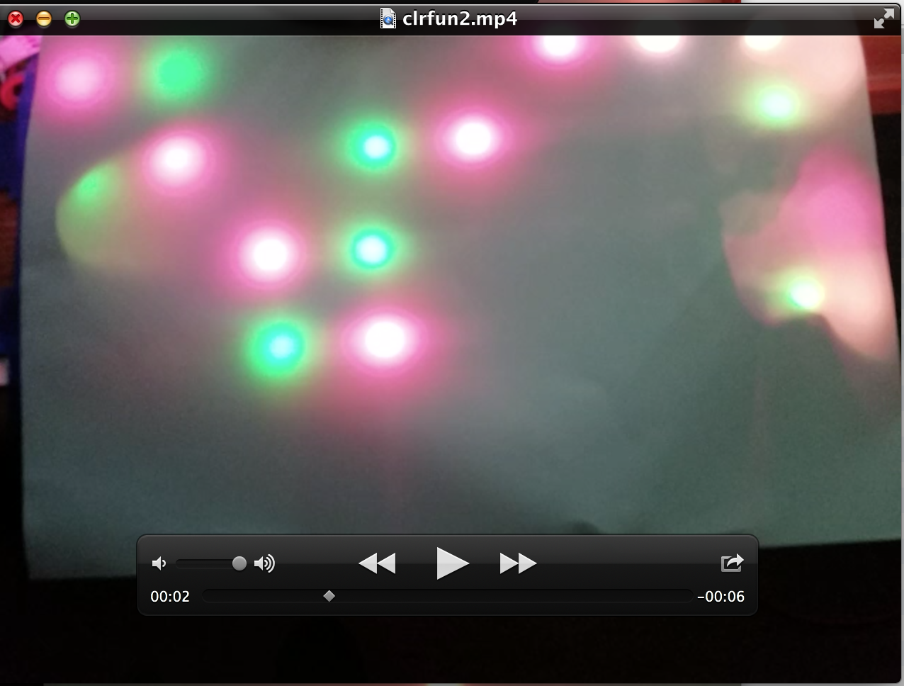
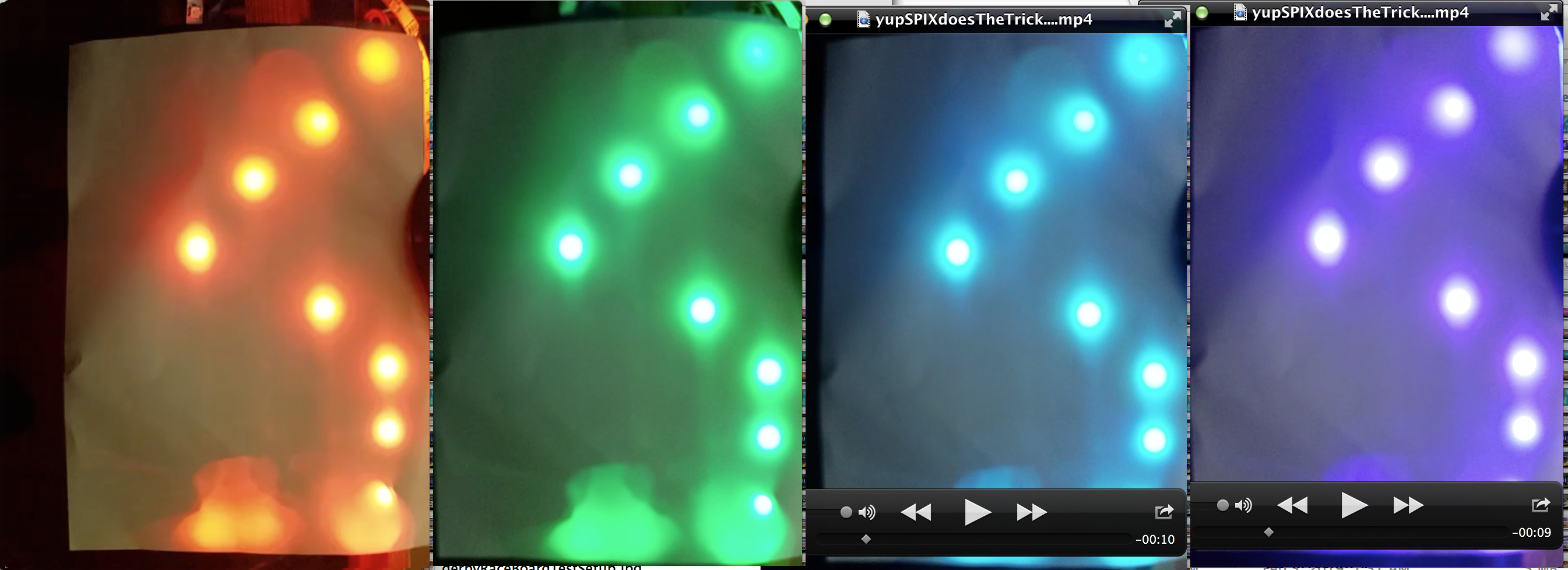
Here it is... regarding orientation: tilt your head to the right to see it landscape... sorry for that... since the shot was straight down, the phone (camera) could not figure out top...
To take (most of) the glare away, I put a white card stock / heavy white paper on the leds.
Btw, orange and red are the 'working colors 0 and 3.
What you can observe is: with multiple colors, color sequence in the string is always the same: zag - odd row - sequence is reverse of zig - even row - sequence, and the middle pixels have the same color and the begin and end pixels have each a different color.
This is a dump of the colors and the buffer - line by line - you can recognize the diagonal line: Tilde
~means dark pixel with color 0, uppercase characterXmeans that R or G or B have a value other than 0. The dump looks for all color the same! There is no graphics.clear() between the drawing of the diagonal with the different color... so no bio-color-perception dependent aliasing - ;-) - or in other words: same algorithm and ultimately integer values for which pixel to paint and which not: always the same 2 pixels except 3 on third row (row 2).0: 1573095 1: 7667850 2: 15144960 3: 51510 0 12345678 0: XX~~~~~~~ 1: ~~XX~~~~~ 2: ~~~~XXX~~ 3: ~~~~~~~XXBuffer dump w/ more details (byte index of RGB tuple begin for even row and end for odd row - and RGB values):
      tuple
      index
         in
row  buffer   R   G   B
------- --- ----------- -----
evn zig   0  54 201   0 true
evn zig   3  54 201   0 true
evn zig   6   0   0   0 false
evn zig   9   0   0   0 false
evn zig  12   0   0   0 false
evn zig  15   0   0   0 false
evn zig  18   0   0   0 false
evn zig  21   0   0   0 false
evn zig  24   0   0   0 false
  0: XX~~~~~~~
odd zag  53   0   0   0 false
odd zag  50   0   0   0 false
odd zag  47   0 201  54 true
odd zag  44   0 201  54 true
odd zag  41   0   0   0 false
odd zag  38   0   0   0 false
odd zag  35   0   0   0 false
odd zag  32   0   0   0 false
odd zag  29   0   0   0 false
 1: ~~XX~~~~~
evn zig  54   0   0   0 false
evn zig  57   0   0   0 false
evn zig  60   0   0   0 false
evn zig  63   0   0   0 false
evn zig  66  54 201   0 true
evn zig  69  54 201   0 true
evn zig  72  54 201   0 true
evn zig  75   0   0   0 false
evn zig  78   0   0   0 false
 2: ~~~~XXX~~
odd zag 105   0   0   0 false
odd zag 102   0   0   0 false
odd zag  99   0   0   0 false
odd zag  96   0   0   0 false
odd zag  93   0   0   0 false
odd zag  90   0   0   0 false
odd zag  87   0   0   0 false
odd zag  84   0 201  54 true
odd zag  81   0 201  54 true
 3: ~~~~~~~XX
Same pattern for all the R G B colors:
#     R   G   B   colorNo
-   --- --- ---  --------
0   231   0  24   1573095
1   138   0 117   7667850
2     0  24 231  15144960
3    54 201   0     51510
Even if I messed up the interpretation of RGB or BGR or what ever, I would expect to show only one color... or max two - one for zig and one for zag... but not three with the inner pixels - if there are more than one as in row 2 - having the same color...
To produce this, setup the neopixel string on B15 w/ a resistor of 330R Ohm between B15 and 5V and upload this code:
// colorfun.js
var npxPin = B15
  , g = Graphics.createArrayBuffer( 9,4,24
            ,{zigzag:true,color_order: "rgb"} )
  , clrs = [1573095,7667850,15144960,51510]
  , cdx  = 0
  , cIId = setInterval(function(){
        g.setColor(clrs[cdx]); g.drawLine(0,0,8,3);
        cdx = ++cdx % 4;
      },1000)
  , sIID = setInterval(function(){
        require("neopixel").write(npxPin,g.buffer);
      }, 500)
  ; pinMode(B15,"af_opendrain");
I also tried w/ no no zig-zag and the color effect is the same... also drawing single lines in horizontal and vertical and +-45 degrees show the same color issue... set pixel does it!
2 Attachments
-
• #4
dithering/smoothing in the graphics buffer display routine? what if you take a "perfect" line exactly matching the dots, ie r1c3, r2c4, r3c5, r4c6
--x------
---x-----
----x----
-----x--- -
• #5
or simply r1c5, r2c5, r3c5, r4c5
----x----
----x----
----x----
----x---- -
• #6
Thought about this... but the colors are so absurd... and how can you smoothen out setting single pixel? ... it is random that left or right of the pixel a green one shows... just weird.
Here the code to your suggestion - and thank you for jumping on this:
// colorfun2.js

// drawing Lines and setting a Pixel in 9 x 4 and 24 bbp
//
//   0 1 2 3 4 5 6 7 8
// 0 L ~ ~ ~ ~ L L L L
// 1 ~ L ~ ~ P ~ ~ ~ L
// 2 ~ ~ L ~ ~ ~ ~ ~ L
// 3 ~ ~ ~ L ~ ~ ~ ~ L

var npxPin = B15
  , g = Graphics.createArrayBuffer( 9,4,24
            ,{zigzag:true,color_order: "rgb"} )
  , clrs = [1573095,7667850,15144960,51510]
  , cdx  = 0
  , cIId = setInterval(function(){
        g.setColor(clrs[cdx]);
        g.drawLine(0,0,3,3);
        g.drawLine(5,0,8,0);
        g.drawLine(8,0,8,3);
        g.setPixel(4,1,clrs[cdx]);
        cdx = ++cdx % 4;
      },2000)
  , sIID = setInterval(function(){
        require("neopixel").write(npxPin,g.buffer);
      }, 250)
  ; pinMode(B15,"af_opendrain");
2 Attachments
-
• #7
I'd be pretty sure that this was actually an electrical issue due to the neopixels missing one or two bits (so one pixel's colour 'bleeds' into the next).
Are you sure the grounding is ok? And do you have an oscilloscope? Are the signals actually 5v?
Out of interest, what happens if you just do:
SPI2.setup({baud:3200000, mosi: npxPin});
SPI2.send4bit(g.buffer, 0b0001, 0b0011);
// edited after @allObjects suggestions
Which is the 'old' style of doing neopixels.
I'm just aware that there was this PR 8 months ago that changed the waveform pattern: https://github.com/espruino/Espruino/pull/1459
There was obviously a lot of testing that went on but given it had been working fine for years beforehand, the phrase "if it ain't broke, don't fix it" could apply here.
-
• #8
HW / wiring all just ok... it was reproducible... no electrical issue what so ev er...
This means that the "neopixl" module has obviously some ick... as code below and clip proof... and kind of surprise is that the colors are quite different...
YYYYYYUUUUUUUUUUUUPPPPP.... plain SPI use fixes it (your option is a bit off... but that's peanuts... and with B15, isn't it SPI2?)
Thanks a lot, @Gordon.
// colorfun3.js

// drawin Lines and setting a Pixel in 9 x 4
//
//   0 1 2 3 4 5 6 7 8
// 0 L ~ ~ ~ ~ L L L L
// 1 ~ L ~ ~ P ~ ~ ~ L
// 2 ~ ~ L ~ ~ ~ ~ ~ L
// 3 ~ ~ ~ L ~ ~ ~ ~ L

var npxPin = B15
  , g = Graphics.createArrayBuffer( 9,4,24
            ,{zigzag:true,color_order: "rgb"} )
  , clrs = [1573095,7667850,15144960,51510]
  , cdx  = 0
  , cIId = setInterval(function(){
        g.setColor(clrs[cdx]);
        g.drawLine(0,0,3,3);
        g.drawLine(5,0,8,0);
        g.drawLine(8,0,8,3);
        g.setPixel(4,1,clrs[cdx]);
        cdx = ++cdx % 4;
      },1000)
  , sIID = setInterval(function(){
        SPI2.send4bit(g.buffer, 0b0001, 0b0011);
      }, 500)
  ; pinMode(npxPin,"af_opendrain");
    SPI2.setup({baud:3200000, mosi:npxPin});
2 Attachments
-
• #9
Thanks - I've just revered that PR, so on the latest builds it should now be working again.
I think I'll have to start manually testing every hardware-related change that comes in before merging - it just takes so much time to do though.
-
• #10
...becoming the Linus trap
-
• #11
Hopefully I won't start hurling abuse at contributors :)
edit: I do really appreciate any contributions to Espruino. However, I do this full time and I'm aware that in a lot of cases (like with the Neopixels) I have a lot of hardware available here that I can test with - its not reasonable to expect others that are suggesting changes to have tested on all the same stuff, so at the end of the day it falls down to me to test things out before merging.
-
• #12
hurling abuse at contributors :)
...did not want to go there and was not really my concern... was more thinking about your and your 'closes' sanity. Nothing wrong with working hard or more than average... but it still should sustain life and not the other way round.
-
• #13
...had some more neopixely color fun with this code... works like a charm... I mean @Gordon 's neopixel implementation... the old way... and in a bit - comes 2v02 - also the new way!
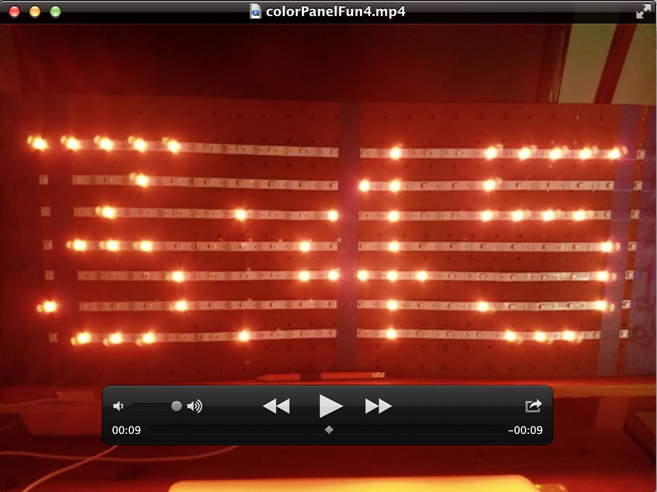
Take a look at the clip showing poor man's video screen... display panel... call it what you want... (this version uses the 30 pixel per m... 60/m is available too and would make it better (and more power hungry. Going for 144/m will almost be 'blowing away'... also the power that goes with it. 144/m is the densest so far. Theoretically 200 is possible by the body of the pixel (<=5mm square), but unfortunately the 'legs' stick a bit out and are thus not that cooperative to reach that density.
// colorfun4.js

// drawing Lines and Text and setting a Pixel in 7 x 20

var npxPin = B15
  , g = Graphics.createArrayBuffer( 20,7,24
            ,{zigzag:true,color_order: "rgb"} )
  , clrs = [1573095,7667850,15144960,51510]
  , cdx  = 0, pdx = 0, dte
  , cIId = setInterval(function(){
        g.clear();
        g.setColor(clrs[cdx]);
        if (pdx < 4) {
          g.drawLine( 0, 0, 5, 5);
          g.drawLine(11, 0,19, 0);
          g.drawLine(19, 0,19, 5);
          g.setPixel(9,3,clrs[cdx]);
        } else if (pdx < 5) {
          g.drawString("Hi -",0,0);
        } else if (pdx < 6) {
          g.drawString("Mike!",0,0);
        } else if (pdx < 8) {
          d = new Date();
          g.drawString(""+(d.getMonth()+1)+"/"+d.getDate(),0,0);
          if (pdx === 6) cdx = (cdx+3) % 4;
        } else if (pdx < 10) {
          g.drawString((""+d.getHours()).substr(-2)+":"+(""+d.getMinutes()).substr(-2),0,0);
          if (pdx === 8) cdx = (cdx+3) % 4;
        } else if (pdx < 11) {
          g.drawString("ooPs",0,0);
        }
        cdx = ++cdx % 4; pdx = ++pdx % 11;
      },1000)
  , sIID = setInterval(function(){
        SPI2.send4bit(g.buffer, 0b0001, 0b0011);
      }, 500)
  ; require("Font6x8").add(Graphics);
    g.setFont6x8();
    pinMode(npxPin,"af_opendrain");
    SPI2.setup({baud:3200000, mosi:npxPin});
2 Attachments
-
• #14
Nice - and wow, that looks bright!
-
• #15
It does look bright. This is turning out to be a great project resurrecting the past.
Here's the artwork the lights will sit behind. An artist's representation (mine) but ten rows with the different colors as in the video of the board. The board is black with the horse cutouts diffused by a frosted clear plastic and the Neopixel lighting behind the horse. I think it will be really nice when completed.
1 Attachment
 allObjects
 Spocki
 Gordon

 matencio
On Espruino-WiFi w/ 2v01, I have a 9 by 4 graphics instance of Graphics with 24 bpp. The graphics is updated on external events. The events are detected by watched and polled pin changes and statuses. For the display panel I use a 5V off-initializing neopixel string in line-by-line zig-zag routing that presents like a dot matrix panel. Since I do not want to use the application driven .flip() of moving the display buffer into the display, I have a function on 250[ms] interval that does it. Because the setup, the .flip like logic is very simple:
On a very regular basis I get random green 'erranding' pixel before or after pixels I'm setting in the string direction . Moving my set pixel along the the string by setting current pixel w/ backround color (0) and next or previous pixel with a constant non-backround color (!0), the green 'erranding' pixel keeps leading or following the changing pixel... weird...
Reading the buffer with a JS function, I never see bleeding. All 3 pixel bytes have always left the old place and show all up at the new place.
Event rate is very low compared to neopixel refresh rate (graphics flip rate). Power supply is 3A. Grounds are connected at Espruino board. There are never more 12 pixels on, never all white. Pin mode is set to af_opendrain and data line is pulled to 5V w/ resistor. I varied the resistor between 1K and 330R w/ no different result.
What could cause that? Even with constant refreshing and no change in the graphics buffer, the green 'erranding' pixel stays put. The 'erranders' or really random... also in regard of the row.