-
• #2
...this is on an Espruino Original?
It's probably because the peripherals run at different clock speeds in different parts of the chip. Even though the chip is running faster, the GPIO will run slower so any accesses will take a few cycles.
Generally because Espruino isn't super fast anyway, the GPIO peripheral clock is lowered more than it has to be so you get better power consumption.
On the F4 boards there's a method called E.setClock where you can tweak it on the fly - however it's not implemented on the F1.
The clock domain you need is for the APB2 bus, and it's called PCLK2. Looks like the default is to divide by 4, and you can change that to use the clock as-is. It's in the
RCC.CFGRregister if you look at the STM32F103 reference manual (if you're interested).Maybe try:
poke32(0x40021004,peek32(0x40021004)&~(7<<11))And see if that helps at all?
-
• #3
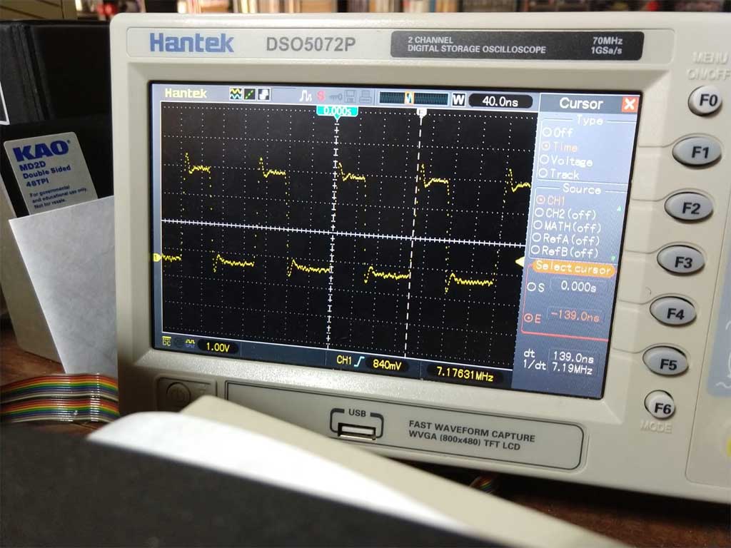
Yesss, that's cut it almost in half, now it's only 139 ns. Are there still wait states for other reasons?
Thanks!
//STM32F103RCT6.pdf -> https://www.st.com/resource/en/reference_manual/cd00171190.pdf
//7.3.2 Clock configuration register (RCC_CFGR)
//Read RCC_CFGR (see section 7.3.2)
var a=peek32(0x40021004).toString(2);
while (a.length<32) a="0"+ a;
a
00000000000111010010110000001010

00000 000 0 0 0111 0 1 00 101 100 0000 10 10

RESERVED: 00000
MCO:        000 -> no clock (Microcontroller clock output)
RESERVED:     0
USBPRE:       0 -> PLL clock is divided by 1.5 (USB prescaler)
PLLMUL:    0111 -> clk*9 (PLL multiplication factor)
PLLXTPRE:     0 -> HSE clock not divided (HSE divider for PLL entry)
PLLSRC:       1 -> Clock from PREDIV1 selected as PLL input clock
ADCPRE:      00 -> PCLK2 divided by 2 (ADC prescaler)
PPRE2:      101 -> HCLK divided by 4 (APB high-speed prescaler(APB2))
PPRE1:      100 -> HCLK divided by 2 (APB Low-speed prescaler(APB1))
HPRE:      0000 -> SYSCLK not divided (AHB prescaler)
SWS:         10 -> PLL used as system clock
SW:          10 -> PLL selected as system clock
*/

//Put 000 into PPRE2
poke32(0x40021004,peek32(0x40021004)&~(7<<11));
1 Attachment
-
• #4
Is it a square wave you want or Is this testing?
You could use the pwm output and not use any loop code at all.
-
• #5
Testing, yes, trying to find where the limits of this little cute chip are. Speaking of which... can I overclock it by setting the PLL multiplier to more than 9x?
-
• #6
Are there still wait states for other reasons?
Not that I'm aware of.
Also, if you just want a crazy fast clock, looks like you can turn on the 'Microcontroller clock output' :)
can I overclock it by setting the PLL multiplier to more than 9x?
Possibly, yes :) I seem to recall that using
setClockon the F4 I tried I could get it from 84 Mhz up to 120 or so.I believe there may be other registers (there were on the F4 IIRC) that allow you to tweak the core voltage up a bit, which will let you hit the higher speeds.
Having said that, you may need to do some fiddling if you want USB to stay working :)
-
• #7
Great! Now I have to learn the sequence of clock source swapping that works to change that, it seems I can't just poke the new multiplier value there, right?
-
• #8
it seems I can't just poke the new multiplier value there, right?
I can't remember... Maybe you can - but you might have to swap the clock source to the internal oscillator, do it, then swap it back...
It might be easier just to make your own build?
 Gordon
 Georg
Georg
 Wilberforce
With this:
loop()
It takes 223 ns to loop once, but three cpu cycles @72MHz are 3*1e9*1/72e6= 41.6 ns, can I touch some clock setting somewhere to make it toggle faster?
Thanks,
1 Attachment