Most recent activity
-

@yayAdrian what do you mean "got a switch" and "channel"? Can you please add more details for what would be done? Thanks
-
-

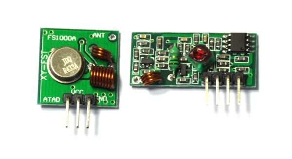
I have the same receiver and transmitter as on this image:

After some tests I found that left one on the image is the transmitter (3 pins) and right one is the receiver (4 pins)I using the code from example, here are my exact code with connections:
/** On press button BTN1 send bits (CODE variable) from transmitter (A1) to receiver (A0) multiple times. Blue LED blinking on send data, green LED blinking on receive data. Transmitter: GND <-> GND VCC <-> Bat ATAD <-> A1 Receiver: GND <-> GND VCC <-> 3.3 (If using Bat there are many errors that we get on input) DATA1 OR DATA2 <-> A0 */ var t,n, counter = 0; // When the signal rises, check if it was after ~5ms of delay - if so (and if we have a code) display it. function sigOn(e) { // console.log('sigOn:', getTime()); var d = e.time-t; if (d>0.005 && n>0) { console.log(counter++, ":0b"+n.toString(2)); n=0; } t = e.time; LED2.write(1); } // When the signal falls, measure the length of our pulse. // If it was within range, record a 1 or a 0 depending on the length. // If it wasn't in range, zero it function sigOff(e) { // console.log('sigOff:', getTime()); var d = e.time-t; t = e.time; if (d>0.0001 && d<0.001) n = (n<<1) | ((d>=0.0004)?1:0); else n=0; LED2.write(0); } setWatch(sigOn,A0,{repeat:true,edge:"rising"}); setWatch(sigOff,A0,{repeat:true,edge:"falling"}); var TX = A1; var CODE = 0b10100000111111101110; function sendCommand(command) { LED3. write(1); var bits = (CODE & ~0b11111) | command; for (var i=24;i>=0;i--) { if ((bits>>i)&1) { digitalPulse(TX,1,0.9); digitalPulse(TX,0,0.3); } else { digitalPulse(TX,1,0.3); digitalPulse(TX,0,0.9); } } digitalPulse(TX,1,0.001); LED3. write(0); } function sendMultiple(command) { var n = 9; var interval = setInterval(function() { sendCommand(command); if (n-- < 0) clearInterval(interval); }, 50); } var socketOn = false; setWatch(function() { socketOn = !socketOn; sendMultiple(socketOn ? 0b11110 : 0b01110); }, BTN1, { repeat:true, edge:"rising", debounce:10 }); // A1 -> transmitter (3 wires) green // A0 -> receiver (4 wires) yellowHope this helps, LMK if you need some help, I passed it before few days. :)
BTW, how did you checked the remote control that it works fine?
PS: Here is additional good explanation for the code if you need it.
-

Let say I tested the PYROELECTRIC MOTION SENSOR to turn on/off the led with Espruino Board, and now I wont to use a simple chip (I need the Espruino board for other experiments :) ) to do this, where to start? Tried to find some manuals but without success. Is there some thing for "Dummies"?
-
-
-
Still didn't tested the remote, it on it's way from Hong Kong , I sending and receiving the bits on the same board :)
But lets try to understand it.
Does each channel sends different code? just try to debug it with console.log()