-
• #2
Hi, I know it says MAX7219 in the description, but it looks from the picture on the Adafruit page like it's actually something else... I think HT16K33.
Adafruit's driver looks quite simple though, so you should be able to get up and running quite quick...
I2C1.setup({scl:B6, sda:B7}); I2C1.writeTo(0x70, 0x21); // turn on oscillator I2C1.writeTo(0x70, 0x81); // disp on I2C1.writeTo(0x70, 0xE0 | 15); // brightness 15 // not sure about this, you may need 16,8,1 var g = Graphics.createArrayBuffer(8,8,2); g.flip = function() { I2C1.writeTo(0x70, 0, g.buffer); }; g.drawLine(0,0,8,8); g.flip(); -
• #3
Thank you so much Gordon! I am so happy to see something come alive!
I used this:
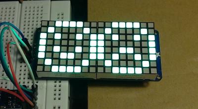
var g = Graphics.createArrayBuffer(16,8,1);To get this result -

Is that what you were expecting?
Also, I'm giving a talk on the state of JavaScript and IoT at Node.js Interactive and at FluentConf next year and I'm showcasing the Pico along with other things!
-
• #4
That's great! It's almost what I was hoping for, but it looks a bit like somehow it's wrapped around so one of the lines is in the wrong place... I was expecting just a diagonal line.
Maybe try some other things with graphics:
g.clear();
g.drawRect(0,0,7,7);
g.flip();
g.clear(); g.drawString("Hi"); g.flip();and see if it's doing the right thing. It might be we have to fiddle with it a bit to get everything lined up.
Maybe try one of these commands in flip instead and see if it fixes it:
I2C1.writeTo(0x70, 1, g.buffer);
I2C1.writeTo(0x70, 2, g.buffer);
I2C1.writeTo(0x70, 7, g.buffer);
I2C1.writeTo(0x70, 14, g.buffer);
When that's done we should turn it into a module :)
It'll be great if you included the Pico in your talks too - thanks! Let me know if i can help out at all.
-
• #5
The horse shoe looking one was
I2C1.writeTo(0x70, 0, g.buffer);I2C1.writeTo(0x70, 1, g.buffer);andI2C1.writeTo(0x70, 7, g.buffer);were off.I2C1.writeTo(0x70, 2, g.buffer);andI2C1.writeTo(0x70, 14, g.buffer);created the L shape.
5 Attachments
-
• #6
It seems 0,0 starts at 0,1 or 1,0.
-
• #7
PaintYourDragon from adafruit said this on Twitter:
It's wired that way for routing reasons; need to ROL or ROR (forget
which).https://twitter.com/paintyourdragon/status/663086330834907136
I don't understand what that means :)
-
• #8
ROR is ROtate Right. ROL is ROtate Left.
Difference to a normal shift is that in a shift all bits move one bit position. The leftmost in a shift left or rightmost in a shift right usually gets a 0.
In a rotation the bits move in a circle: in a left shift bit 7 moves into bit 0.
See here: https://en.wikipedia.org/wiki/Bitwise_operation#Rotate_no_carry -
• #9
So do I have to do a bit wise operation on the buffer?
-
• #10
Thanks for the pics - that really clears it up!
It's a bit hacky of them to fiddle the wiring like that!
So yes, looks like you have to do a bitwise operation - but it's not too painful. Something like:
// rotate right I2C1.writeTo(0x70, 0, (new Uint8Array(g.buffer)).map(function(a) { return (a>>1)||(a<<7); })); // or you might need to rotate left I2C1.writeTo(0x70, 0, (new Uint8Array(g.buffer)).map(function(a) { return (a>>7)||(a<<1); })); -
• #11
Thanks for getting me this far!
return (a>>1)||(a<<7);This rotated the pixels correctly except for one last issue...
I can draw a line, I can set a pixel anywhere in the grid.
If the left most
xis on0and it doesn't share the row with another pixel it will show up. If it does share with another pixel, it switches off.g.clear(); //face top g.setPixel(2,0); g.setPixel(3,0); g.setPixel(4,0); g.setPixel(5,0); g.setPixel(1,1); g.setPixel(6,1); //face left g.setPixel(0,2); g.setPixel(0,3); // Won't show because of eyes on 2 and 5. g.setPixel(0,4); g.setPixel(0,5); //eyes g.setPixel(2,3); g.setPixel(5,3); //face right //g.setPixel(7,2); //g.setPixel(7,3); //g.setPixel(7,4); //g.setPixel(7,5); //face bottom g.setPixel(2,7); g.setPixel(3,7); g.setPixel(4,7); g.setPixel(5,7); g.setPixel(1,6); g.setPixel(6,6); g.flip();
If I comment out the eyes the left most pixel will show:
g.clear();
//face top
g.setPixel(2,0);
g.setPixel(3,0);
g.setPixel(4,0);
g.setPixel(5,0);
g.setPixel(1,1);
g.setPixel(6,1);

//face left
g.setPixel(0,2);
g.setPixel(0,3); // Won't show because of eyes on 2 and 5.
g.setPixel(0,4);
g.setPixel(0,5);


//eyes
//g.setPixel(2,3);
//g.setPixel(5,3);

//face right
//g.setPixel(7,2);
//g.setPixel(7,3);
//g.setPixel(7,4);
//g.setPixel(7,5);

//face bottom
g.setPixel(2,7);
g.setPixel(3,7);
g.setPixel(4,7);
g.setPixel(5,7);
g.setPixel(1,6);
g.setPixel(6,6);

g.flip();
-
• #14
Sorry, I made a really stupid typo I'm afraid...
return (a>>1)||(a<<7);should be:
return (a>>1)|(a<<7);||is a logical OR, but|is a binary one that works on all bits. Glad you got it sorted though!There's a bit of info on writing and submitting modules here: http://www.espruino.com/Writing+Modules
For displays, we generally just just create an
exports.connectfunction and then return the Graphics object we created withflip()function added... then everything works the same way. -
• #16
Hey Kylir
I created an NPM module...you can check it out here:
https://www.npmjs.com/package/espruino-adafruit-led-backpackFeel free to contribute additional functionality via GitHub :)
But I have the basics of drawing implemented :)
Regards
Andrew -
• #17
@chalkers thanks! You know you can use Espruino's built-in graphics library, rather than using your own?
var g = Graphics.createArrayBuffer(8,8,1);
// g.buffer is now a Uint8Array with 8 bytes, one for each row
// You might even be able to use your existing code with matrix.drawBitmap(g.buffer)
It's got rotation, fonts, lines, etc etc.
-
• #18
The module uses a similar API to what the arduino library had for the backpack. It uses the graphics API in the module :)
-
• #19
This is pretty awesome, guys! I recently bought the 16x8 backpack and I'd be happy to extend the code and test it with that backpack (if I find the time).
-
• #20
 Gordon
 chalkers
 HaraldK
 Kylir
Kylir pedesen
I purchased this Small 1.2" 8x8 Ultra Bright Square White LED Matrix + Backpack.
I got it working with an Arduino to make sure everything is wired up correctly and it does work.
https://vine.co/v/eLx5pq7zAhK
I believe it uses the MAX7219 driver but can't get it to work. Adafruit uses I2C and the Espruino library uses SPI.
Is there any raw I2C code I can use to test it out. I've wired up the - + to GND and 5v, and C to B6 and D to B7.
Thanks