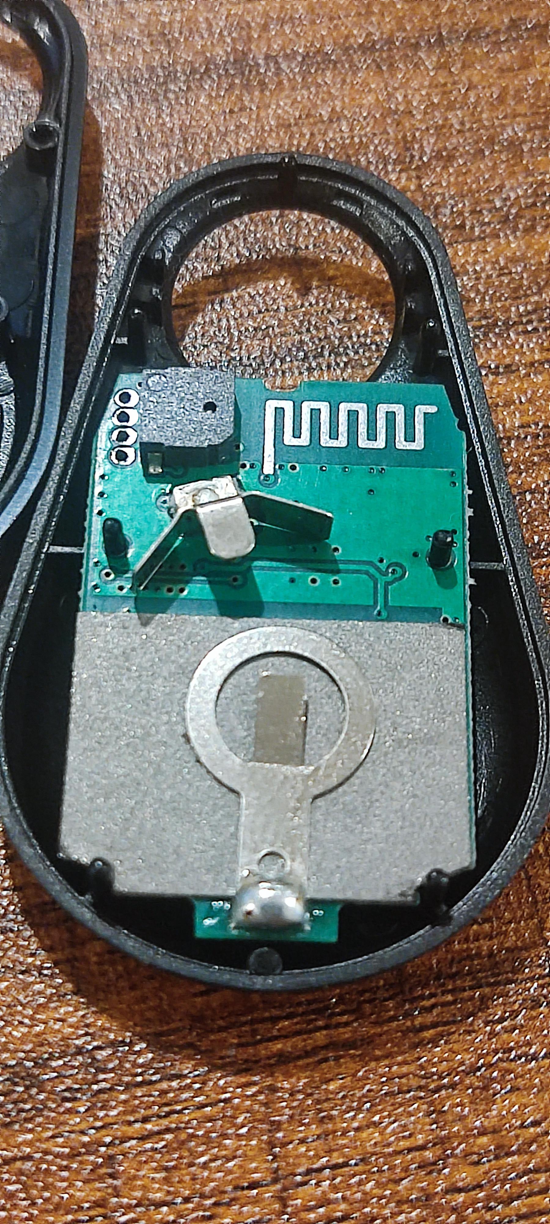
-
Sure, here you go.
There's this grey thick sticker (maybe insulation rf shield?) behind the battery which could be where the nfc antenna are?).
Not sure about the LEDs; I've looped through all the 32 pins and they are the only ones that light up. It's possible it's RGB but the LED module itself (near the top of the first picture) has four traces; two beside each other (which are likely the D17 and D20 pins) one going to a via and one going to what are probably resistors.
1 Attachment
You are reading a single comment by @parasquid and its replies.
Click here to read the full conversation.
 parasquid
Thanks, looks like optional 32kHz crystal is there too and enabling DC/DC regulator is supported too (reference schematics here). Don't see nfc pins going anywhere, maybe on the other side? Coul you perhaps make a photo of the other side too?
The led may be RGB so maybe third pin could be connected too? two or three gpios next to swd pins (D22,23,24) look grounded, maybe it could be cut and connected to blue LED instead.