-
• #2
Do you have a photo of it?
Also, when you attach power to it, does the red led blink? Can you enter bootloader mode by holding the button while applying power? (the green LED should be on constantly in bootloader mode)
-
• #3
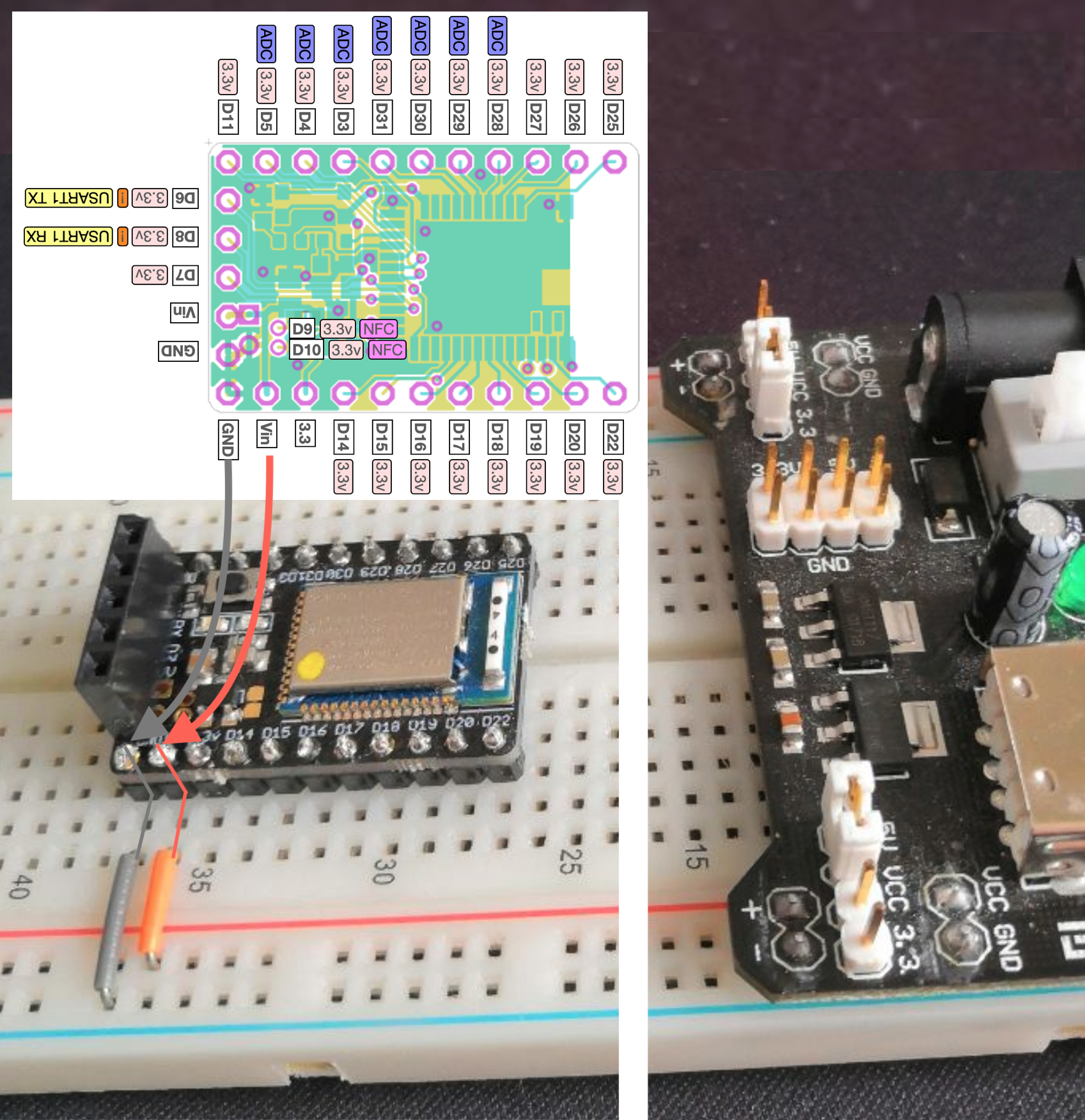
this is my current circuit

No LED lights up at all, though it did when I first connected it to power after soldering, but I couldn't get it to connect with bluetooth, and then it stopped doing anything at all and stopped lighting up. -
• #4
Is it possible you might have accidentally connected the 3.3v power input on the module to 5v from the breadboard supply? If so that'd do the sort of thing you're experiencing - working for a bit and then breaking...
-
• #5
you seem to have that right side power jumper connected to 5v side. it is 5v,gnd,gnd,3.3 so in the middle it is off, left two is 5v, right two is 3.3V
-
• #6
It looks good to me when comparing with the reference on http://www.espruino.com/MDBT42Q page... What does not look so favorable to me is the shape and surface structure of the soldering points: somehow they look like having had a cold... no flow ;-)
Mend the soldering points w/ fluxed tin that it flows, then try again. - I hope you did not - before - connect by accident the wrong way or some 'flailing' wires touched in unfavorable locations ;-)
1 Attachment
-
• #7
As mentioned the power rail is fed from 5V so this might be the real issue. I have this breadboard power adapter too, it is nice that you can have both 3.3V and 5V on different sides of breadboard but it is easy to mix it.
1 Attachment
-
• #8
Oh, sorry, maybe it is OK? I now see it is connected to the VIN pin and that one can accept 5V as there is voltage regulator on that MDBT42Q board. So please ignore my posts :-)
-
• #9
I connected it to 5V after I wasn't getting much success with getting the MDBT42Q to connect over bluetooth or Serial, and i made sure to only use the VIN Pins to connect power, and made sure to not leave and cables flailing around
-
• #10
Do you think you could check the voltage between GND and 3.3v on the MDBT42 breakout's pins with a volt meter? That'd help to narrow down if it's the voltage regulator on the module that is blown, or something else.
Also, did you try just powering it up with the button held down to see if any lights light up?
-
• #11
I'm measuring 2.4V between GND and 3.3V when i put my power adapter on 3.3V, and 2.7V when i put it on 5V, and I'm measuring 2.5V between GND and V of the power adapter when the MDBT42Q is disconnected, and 6.7V when it's on 5V with the MDBT42Q disconnected. I have a 9V 1.2A power supply connected to the power adapter.
The lights are also off when powering it up with the button held down. -
• #12
Ok, so with the MDBT42 connected, what do you measure between GND and Vin on the MDBT42? So the grey and orange wires.
Or was that what you meant with 2.5v? If so it sounds like something is wrong with your power supply board.
-
• #13
i measure 2.4V with 3.3V, and 6.3V with 5V between the GND and Vin pins on the MDBT42Q
-
• #14
Before I soldered headers on to it, I wrapped wires through the holes in the PCB, and was able to somewhat use it with the same power adapter.
-
• #15
6.3V with 5V between the GND and Vin pins on the MDBT42Q
I'm not sure I understand - so you're saying that the wires on your breadboard power supply that should supply 5v are actually supplying 6.3v?
-
• #16
yes, and up to 6.7V when the MDBT52Q is disconnected, even though I'm supplying less power than the supply is rated for.
-
• #17
This sounds really broken. It's hard to know if this matters or not with the supply you have, but is it possible that you've got a 9v AC supply plugged into it, when it is expecting a DC supply?
-
• #18
I've never thought of that, but it turns out that it was an AC supply i had plugged into it the whole time
-
• #19
with a DC supply, i get 3.3V correctly at all points, but 8V on 5V
-
• #20
but 8V on 5V
It might be the voltage regulator on the power supply board has blown up then?
You say you get 3.3v correctly - you mean you get 3.3v on the MDBT42 breakout's 3.3v wire as well?
If it's not working now, I'm afraid it may well be blown up. If the power supply board wasn't meant for AC, and was outputting negative 9v straight into the MDBT42 breakout, there's no way it's meant to survive that kind of punishment.
-
• #21
So if you are now sure 3.3V is working, you may try to connect it directly to 3.3 pin on the board and avoid voltage regulator on MDBT42 breakout? This was the way I initially thought you might be using, didn't notice you have 3.3V source but still use 5V via MDBT42 regulator instead. This might help if MDBT42 voltage regulator is not working but nrf52 is still OK.
 Gordon
 OmegaRogue
 fanoush
 allObjects
I soldered headers onto my MDBT42Q from the BangleJs Kickstarter and flashed the latest firmware, after which I haven't been able to get it to connect to my PC anymore.