-
• #2
Yes, you could probably do something like that - but how about dynamically swapping SPI/I2C to some of the other pins the device can output, or just using software SPI/I2C?
Software SPI particularly is actually quite fast.
-
• #3
All right, I'll have to test it & come back with the results ;)
If I understand you correctly, your suggestions ( software spi or pin swapping ) won't help reduce the number of pins used, right ?
Or by 'pins swapping', do you mean declaring software or hardware spi/i2c but with a different pin for the clock signal so as to only have the device(s) with this clock pin connected to actually received data ?
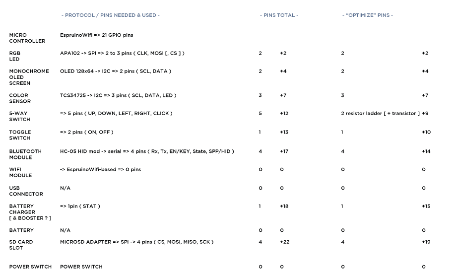
See the attached image for the list of pins I need to connect everything to the Espruino Wifi
To "optimize" the pins mapping ( and at least get below 21 ;) ), I was thinking of a way to free 3 pins while still allowing the use of 'setWatch()' for the 5-way switch, but this may or not work at all depending on if I can manage to get just the right resistor values AND have the transistor go saturated for every button ( maybe by wiring it's base to each button output, not only the last one ? .. )
-> see the following link on this subject ( if one's kind enough to get "correct" values, I'd be happy to return the favor ;p ) https://www.tinkercad.com/things/9egZEDSHPMv-exquisite-crift-inari/editel?tenant=circuits?sharecode=Srm7jaS-vy22K2qTF8z6q6bGo-_pqyLyWWvrb9ZA5SY=I'm thinking of another way to doing so but didn't take the time to write them down or have a try on them ( .. )
Can wait to have everything fit on the EspruinoWifi pins in one way or another & hope my program fits in the memory before finally trying this project .. finger's crossed :)
' be posting updates on the spi/i2c APA thing & the 5-way switch as soon as can do ;)
1 Attachment
-
• #4
I just tested something like http://www.reuk.co.uk/wordpress/wp-content/uploads/2013/09/selector-switch-resistor-ladder-adc.jpg, but:
- 1: those resistor values don't get me "good" results for some reason when reading analog from A1
- 2: I'm not sure wiring a transistor in series with a 10k resistor with Collector on +3.3V & Emitter on A0 'll effectively give me ( for correct resistor value for 1 ) sort of an 'analogWatch' via 2 pins ?
I'm using the following code for my tests:
// pin 0 has the digital watch on it - we may change the pinMode if needed
pinMode(A0, "input_pulldown"); setWatch(function(e) { console.log('A0 pressed'); }, A0, { repeat:true, edge:'rising', debounce:100 });

// first thing I tried ;)
var N = 20;
var voltage = 0;
for (var i=0;i<N;i++) {
  voltage += analogRead(A1)*3.3/N;
}
console.log('voltage: ' + voltage);

// when reading, get the biggest val (mod from @MaBe's  "analogReadMedian()" )
analogReadBiggest = function(p, sampleCount) {
  var i, median;
  var samples = Math.floor(sampleCount);
  var analogValues = new Array(samples);
  // read analog values into array
  i = samples;
  while(i--) analogValues[i] = analogRead(p);
  //sort array, smalest first and largest last
  analogValues.sort(function(a, b){return a-b;});
  return analogValues[analogValues.length-1]; // return biggest
};
I guess I'll have to be more cautious on the length of the wires used between uC & the resistors to have something ~constant in this circuit, hoping the erroneous readings come from that ..
---- update ----
My last try for today, unsuccessful :/// trying to get this 5-way switch from 5 pins down to 1 digital // ( for setWatch() ) & one analog ( to read the five different values through different resistors ) // pin 0 has the digital watch on it pinMode(A0, "input_pulldown"); setWatch(function(e) { console.log('A0 pressed'); console.log('A1 biggest is: ' + analogReadBiggest(A1, 1000)); console.log('A1 lowest is: ' + analogReadLowest(A1, 1000)); }, A0, { repeat:true, edge:'rising', debounce:100 }); pinMode(A1, "input"); // has external 10k pulldown resistor // pin A1 has a 10k pulldown & various pullup resistors depending on the "path travelled" for 5-way switch // to get the biggest val analogReadBiggest = function(p, sampleCount) { var i; var samples = Math.floor(sampleCount); var analogValues = new Array(samples); // read analog values into array i = samples; while(i--) analogValues[i] = analogRead(p); return analogValues.sort(function(a, b){return a-b;})[analogValues.length-1]; // return biggest }; analogReadLowest = function(p, sampleCount) { var i; var samples = Math.floor(sampleCount); var analogValues = new Array(samples); // read analog values into array i = samples; while(i--) analogValues[i] = analogRead(p); return analogValues.sort(function(a, b){return a-b;})[0]; // return lowest }; // for a 10k pulldown, we get the below ( erratic ) outputs // 1: // 10k & nothing ( 500 readings using analogReadBiggest) -> 0.00537117570 // 10k & nothing ( 500 readings using analogReadLowest) -> 0.00512703135 // 2: // 10k & 10k ( 500 readings using analogReadBiggest) -> 0.00537117570 // 10k & 10k ( 500 readings using analogReadLowest) -> 0.00561532005 // 3: // 10k & 2.2k ( 500 readings using analogReadBiggest) -> 0.00512703135 // 10k & 2.2k ( 500 readings using analogReadLowest) -> 0.00512703135 // 4: // 10k & 3.2k ( 500 readings using analogReadBiggest) -> 0.00537117570 // 10k & 3.2k ( 500 readings using analogReadLowest) -> 0.00537117570 // 5: // 10k & 5.7k ( 500 readings using analogReadBiggest) -> 0.00512703135 // 10k & 5.7k ( 500 readings using analogReadLowest) -> 0.00512703135Hoping to have a clearer view of the troubles in the morning ;)
++ - 1: those resistor values don't get me "good" results for some reason when reading analog from A1
-
• #5
Or by 'pins swapping', do you mean declaring software or hardware spi/i2c but with a different pin for the clock signal so as to only have the device(s) with this clock pin connected to actually received data ?
I hadn't really considered that, but yes, that would work great.
For the SD card you have a chip select pin so that might give you something you can use as well?
I'm using the following code for my tests:
Sounds like a good plan with the resistors + analog. I'd say don't use an internal pulldown as it won't work with analogRead (iirc), and make sure that when pressed the voltage changes from 0v to above 1.7v to make sure you get a reliable setWatch.
Also remember that to get
analogReadto work you may need to set the mode toanalog- or just usepinMode(A0)to set the mode back to auto before using analogRead.And to get reliable analog readings you may want a (small) capacitor between GND and A0.
You may also be able to put the battery charge status and/or toggle switch on exactly the same A0 pin as well. If your 5 voltages are 2v,2.25v,2.5v,2.75v and 3v then if the toggle switch varied the voltage by 0.05v you could detect that.
-
• #6
Hi there !
I hadn't really considered that, but yes, that would work great.
Actually, I thought about it when reading your suggestion ;p
For the SD card you have a chip select pin so that might give you something you can use as well?
Indeed: it also gives me a ( silly ? ) idea: using the SDCARD SPI CS pin as the pin on which to set the APA102 SPI CLK () so that the APA102 CLK 'll be tied low while the SD card is in use ? ( so by writing to the SD, it shall auto-disable the APA102 comm ? I guess it'd be even better than tying the SD CS pin to Gnd & then doing the above 'different pin for the clock signal' hack ? )
-> I gotta try those tomorrow ;)Onto the "2pins analog setWatch" hack, I had some success with a quite simple circuit in which the A0 pin ( on which a digital setWatch() is set ) is connected directly to the A1 pin, used as analog input.
An external 10k pulldown & setting it as "analog" did the trick on giving me slightly more meaningfull results :)
In order to get reliable results ( and this, without an added transitor as I first planned ), the least voltage I get is 2.09V ( so some safety from 1.70 ;p )
I didn't try ( yet ? ) adding a "small" ( 1 uF ? ) cap - how would it "smooth" the result ?put the battery charge status and/or toggle switch on exactly the same A0 pin as well. If your 5 voltages are 2v,2.25v,2.5v,2.75v and 3v then if the toggle switch varied the voltage by 0.05v you could detect that.
I'm not sure yet if my setup is precise enought & on how to implement that ( for either the batt. status pin, the toggle, or both ? .. - I plan to use the MCP73831 's stat pin as battery status pin, for info .. )
Now, the voltages I currently get ( from the resistor values I could find around easily ) are the ones in the following code, I'm currently happy with those ( seems to work flawlessly ), but if anyone has hints on better resistor values, I'm a taker ;)
nb: I'm not quite sure of the followings ( gotten using successive tries on tinkercad .. ), but these may be the resistor values you had in mind to produe your proposed voltages ?
( all the followings uses a 10k pulldown as R1 )
3.3Vin-> 3Vout => R2: 1315 Ohms
3.3Vin-> 2.75Vout => R2: 2350 Ohms
3.3Vin-> 2.5Vout => R2: 3600 Ohms
3.3Vin-> 2.25Vout => R2: 5100 Ohms
3.3Vin-> 2.00Vout => R2: 7000 OhmsSo, here's some wip working code :)
// trying to get this 5-way switch from 5 pins down to 1 digital
// ( for setWatch() ) & one analog ( to read the five different values through different resistors )

// pin 0 has the digital watch on it
pinMode(A0, "input_pulldown");
//pinMode(A1, "input"); // has external 10k pulldown resistor
pinMode(A1, "analog"); // has external 10k pulldown resistor -> yup, I am DUMB !
/*
setWatch(function(e) {
  console.log('A0 pressed');
  console.log('A1 biggest is: ' + analogReadBiggest(A1, 1000));
  console.log('A1 lowest is: ' + analogReadLowest(A1, 1000));
}, A0, { repeat:true, edge:'rising', debounce:100 });
*/

// wip 'analog2pinWatch'
function setWatchA(digitalPin, analogPin, callbackFcn){
  setWatch(function(e) {
    callbackFcn(analogRead(analogPin)*3.3);
  }, digitalPin, { repeat:true, edge:'rising', debounce:100 });
}
// usage:
setWatchA(A0, A1, function(buttonAnalogVal){
  console.log('button on A0 pressed: analog read =' + buttonAnalogVal);
  if(buttonAnalogVal > 3.15) console.log('btn1');
  else if(buttonAnalogVal > 2.85) console.log('btn2');
  else if(buttonAnalogVal > 2.50) console.log('btn3');
  else if(buttonAnalogVal > 2.30) console.log('btn4');
  else if(buttonAnalogVal > 2.00) console.log('btn5');
  //else if(buttonAnalogVal > 1.70) console.log('btn6'); // N/A for 5-way switch ..
});

// for a 10k pulldown & pinMode(A1, "analog"), we get the below outputs
// 1:
// 10k & nothing  ( 500 readings using analogReadBiggest) -> 0.99708552681 | *3.3 = 3.29038223847
// 10k & nothing  ( 500 readings using analogReadLowest) ->  0.99781795986 | *3.3 = 3.29924467841
// 2:
// 10k & 1k ( 500 readings using analogReadBiggest)     ->   0.90626382848 | *3.3 = 2.99067063398
// 10k & 1k ( 500 readings using analogReadLowest)     ->    0.90553139543 | *3.3 = 2.98825360491
// 3:
// 10k & 2.2k ( 500 readings using analogReadBiggest)     -> 0.82032501716 | *3.3 = 2.70707255662
// 10k & 2.2k ( 500 readings using analogReadLowest)     ->  0.82008087281 | *3.3 = 2.70626688027
// 4:
// 10k & 3.2k ( 500 readings using analogReadBiggest)     -> 0.75660334172 | *3.3 = 2.49679102767
// 10k & 3.2k ( 500 readings using analogReadLowest)     ->  0.75611505302 | *3.3 = 2.49517967496
// 5:
// 10k & 4.7k ( 500 readings using analogReadBiggest)     -> 0.67969787136 | *3.3 = 2.24300297548
// 10k & 4.7k ( 500 readings using analogReadLowest)     ->  0.67896543831 | *3.3 = 2.24058594642
// 6:
// 10k & 5.7k ( 500 readings using analogReadBiggest)     -> 0.63526359960 | *3.3 = 2.09636987868
// 10k & 5.7k ( 500 readings using analogReadLowest)     ->  0.63648432135 | *3.3 = 2.10039826045
// 7:
// 10k & 10k  ( 500 readings using analogReadBiggest)     -> 0.50074006256 | *3.3 = 1.65244220644
// 10k & 10k  ( 500 readings using analogReadLowest)     ->  0.50074006256 | *3.3 = 1.65244220644

// R: currently testing with A0 wire going directly to A1 'line' ( that is, without any transistor )
// when helding a button pressed:
// 1:
// A1 biggest is: 0.99977111467
// A1 lowest is: 0.99977111467
// 2:
// A1 biggest is: 0.88697642481
// A1 lowest is: 0.88966201266
// 3:
// A1 biggest is: 0.78223849851
// A1 lowest is: 0.78590066376
// 4:
// A1 biggest is: 0.71729610131
// A1 lowest is: 0.71705195696
// 5:
// A1 biggest is: 0.63062485694
// A1 lowest is: 0.62940413519
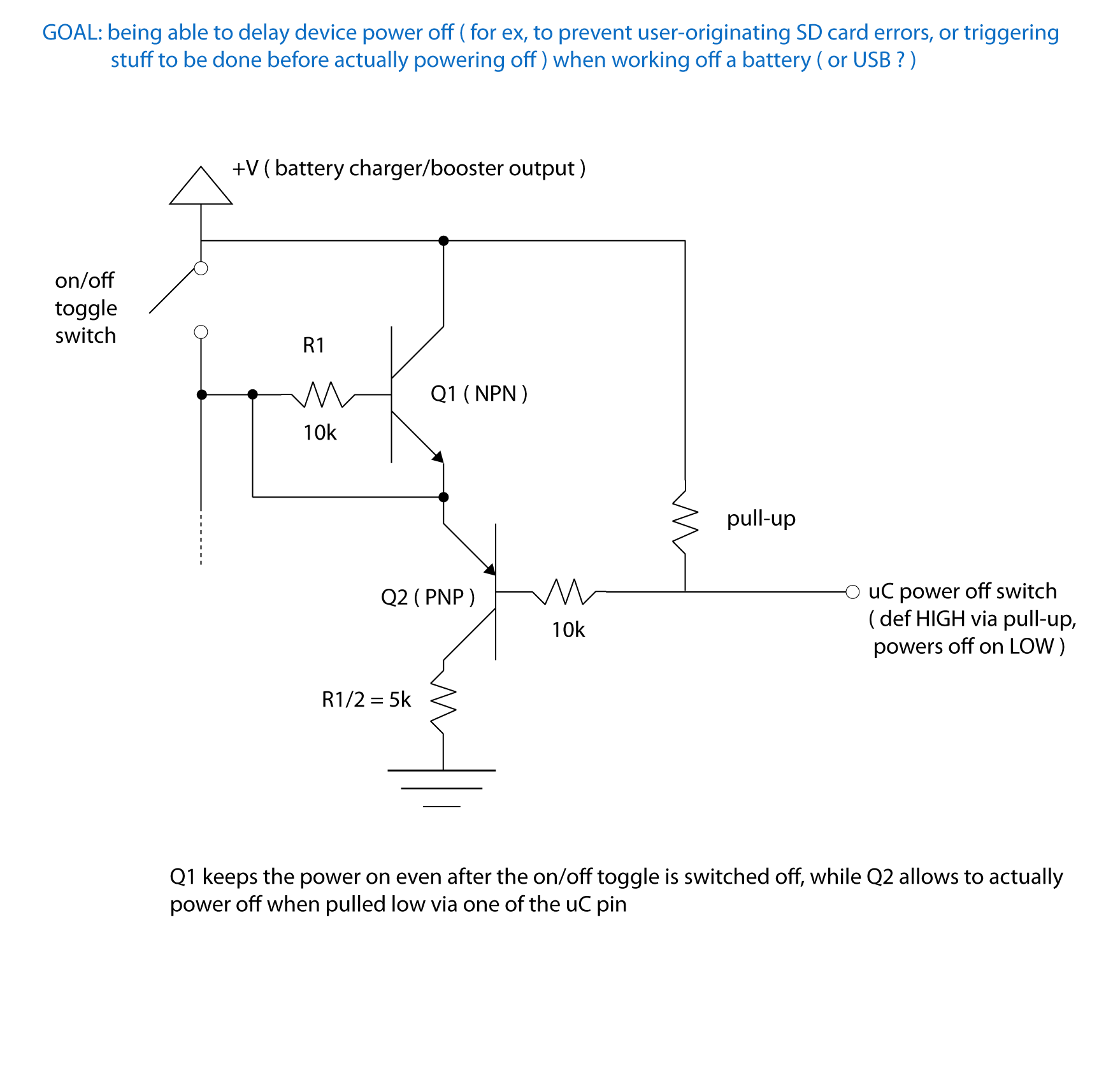
This being said, I'm onto drawing a little "delayed power off" circuit that may be useful to get on one ( not shared ) pin as well ;)
Thanks for the precious hints :)
+ -
• #7
adding a "small" ( 1 uF ? ) cap - how would it "smooth" the result ?
The ADC in the chip expects quite a low resistance to get accurate results (since otherwise the act of switching in the ADC itself would cause the voltage to drop) - so the capacitor gives you that low resistance :) It may not actually be an issue here at all - it's usually for 100k+, and you're not looking to get loads of accuracy (I guess even just 6 bits would do you pretty well).
-
• #8
Hi
I just tried with different "small" caps ( 1pF, 100nF, 1uF ), yet it seems I don't get any changes in the output ( as without, *3.3, I get "X.YZnnnn" where X & Y are constant, Z seems to be +/- 1 & n's are not constant whatsoever .. )
-> I'm currently finishing the "delayed power off" thing, posting it right after it's done & then onto testing those SPI sharedp ins hacks ;)
-
• #9
So !
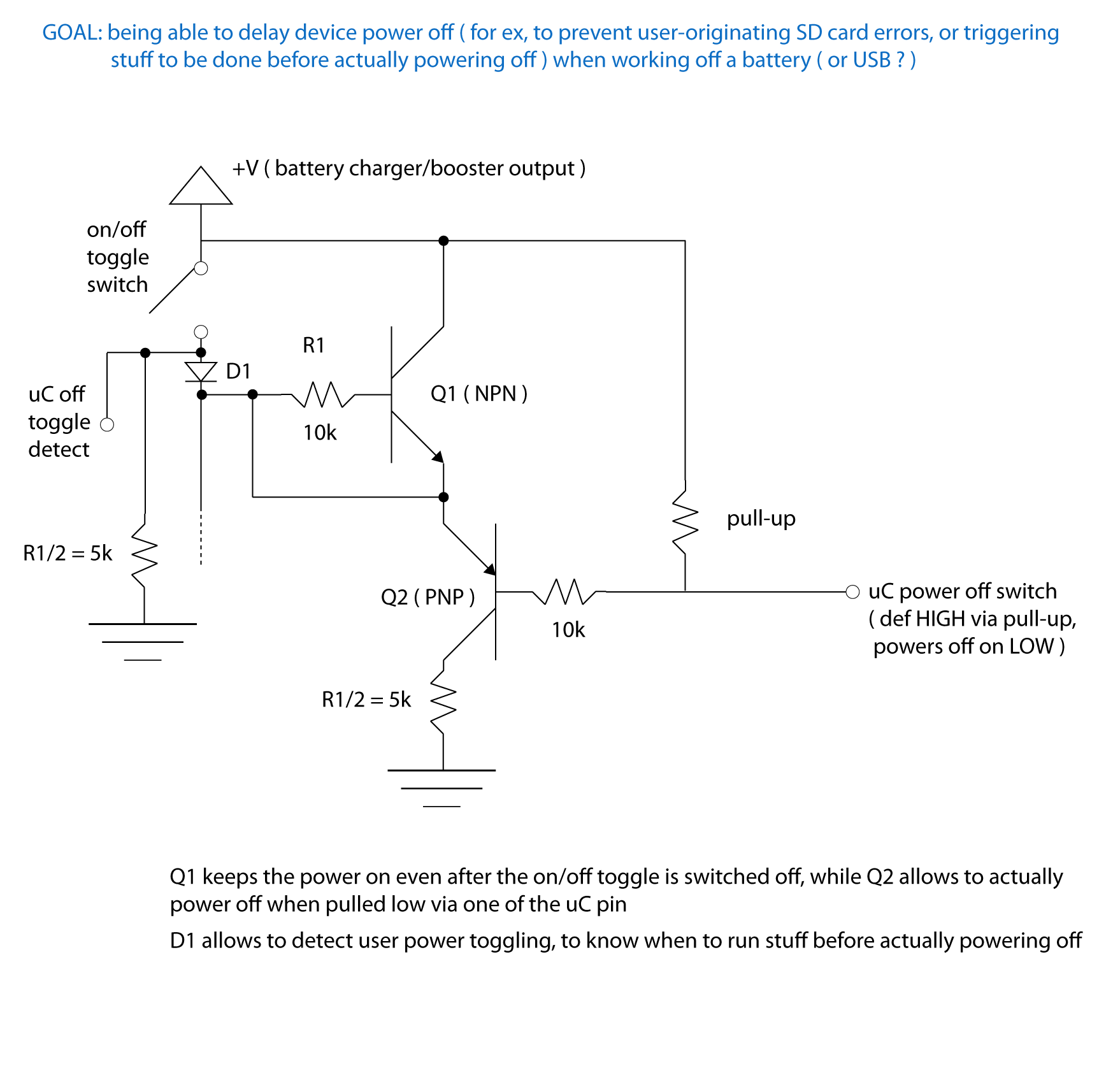
here's the "delayed power off" thing, but I'm wondering what'd be the best alternative to the D1 diode ( to lessen any voltage drop ), aside from that, I guess/hope "correct" resistor value + those 2 transistors 'll do the trickNow, to be able to use the above circuit, I'll need 2 pins .. so I better go trying the "shared SPI pins" before planning on doing so ;p
2 Attachments
-
• #10
Does it matter about voltage drop across D1? As soon as the microcontroller is powered on it can turn Q1 on, which will remove the voltage drop anyway?
But I'd just use a schottky diode? About 0.3v voltage drop?
 Gordon
 stephaneAG


Hi !
To increase the number of available pins on the Espruino Wifi ofr a current project, I wish to share the I2C & SPI bus for several peripherals:
On the I2C side:
On the SPI side:
I had a quick thnk on 'may-be solutions', but I'd be glad receiving further advices before not knowingly messing around
The following drawing is for the SPI side of things, but I wonder if fiddling with the I2C CLK would lead to same behavior ?
Thanks in advance :)
++
1 Attachment