-
• #2
See my board friendly coerced ESP8266 ...friendly and coerced is kind of an oxymoron... but in this case, a good one ;-)
-
• #3
The original Espruino board has an SMD area where I put a FRAM / EEPROM on...
-
• #4
I think flash/eeprom memory, motor drivers, and FET transistors are probably the main uses for it at the moment.
I'm afraid there's no specific document on it, but there are a few pages that include instructions, like:
-
• #5
I thought at some point I put pictures of an AT24 mounted on an Espruino board (the original ones), in the SMD prototyping area. But I can't find the pictures on http://www.espruino.com/AT24 - I thought I'd put them up there. The AT24/AT25 and compatible EEPROM/FRAM chips work great there, and I think both of my original Espruino's have AT24's mounted on them.
Hardware wise, the larger SPI flash chips (like the ones used on the ESP8266 modules to store the firmware) would also work - but I don't think we have a JS module for them yet.
-
• #6
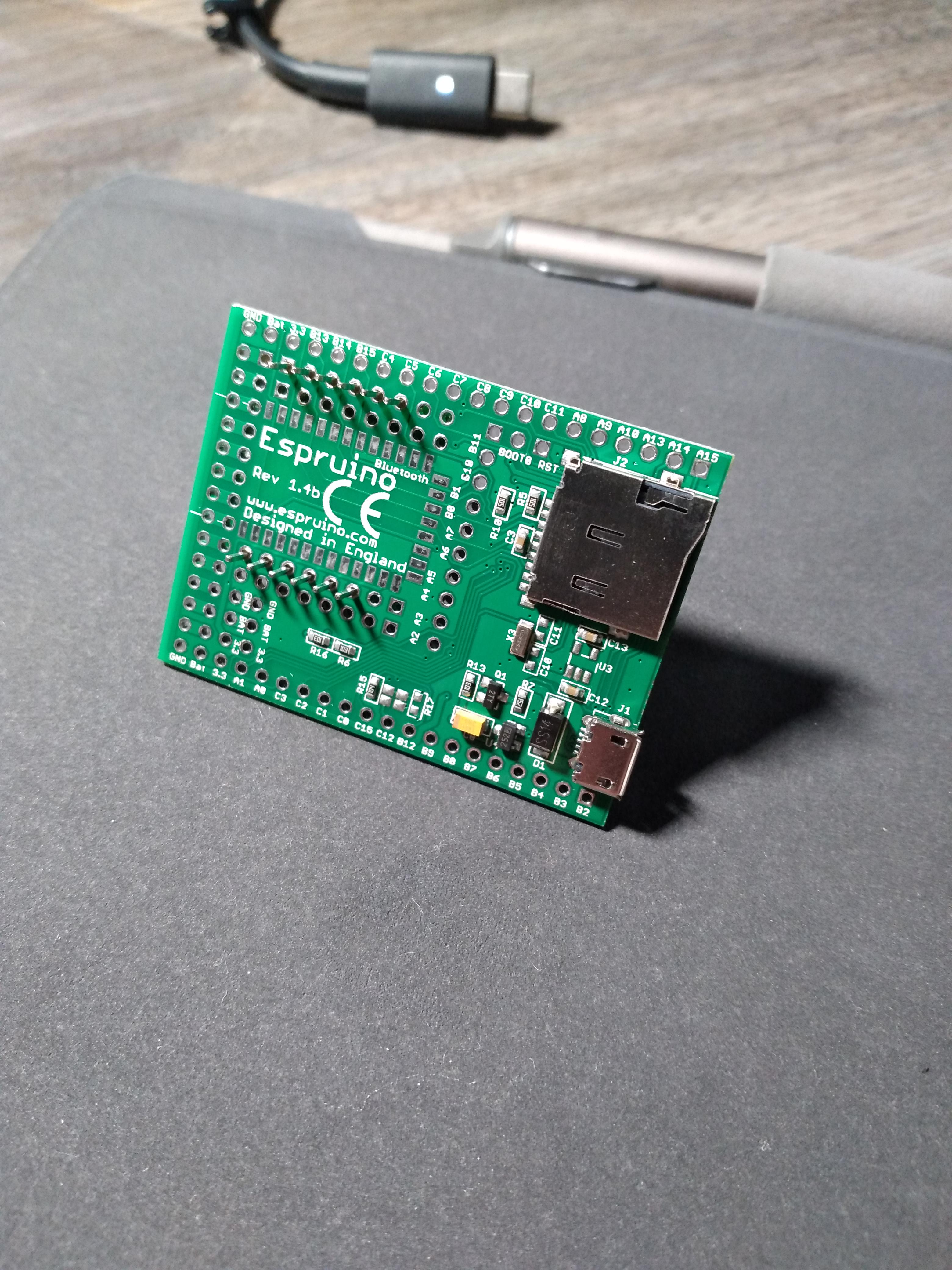
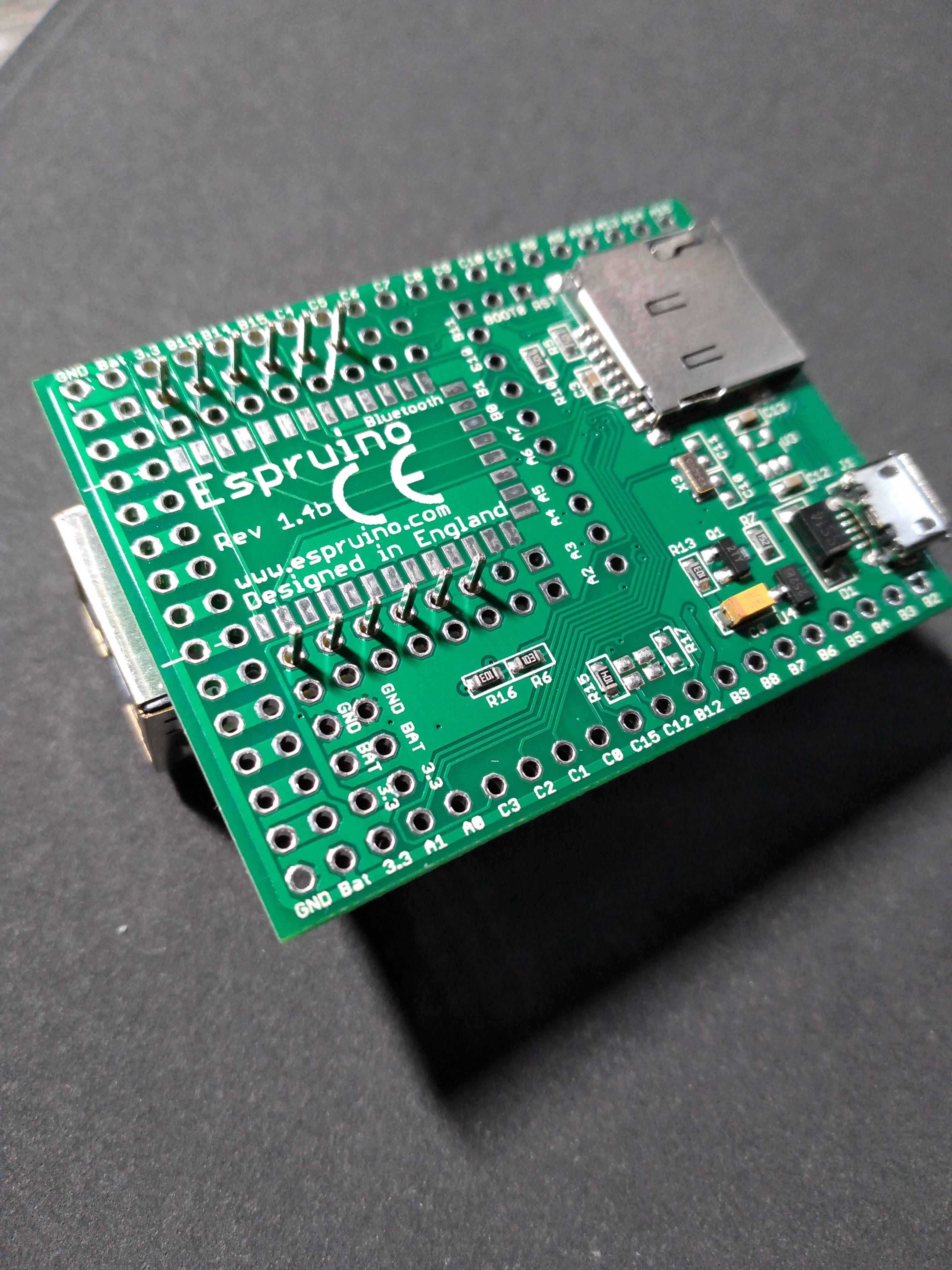
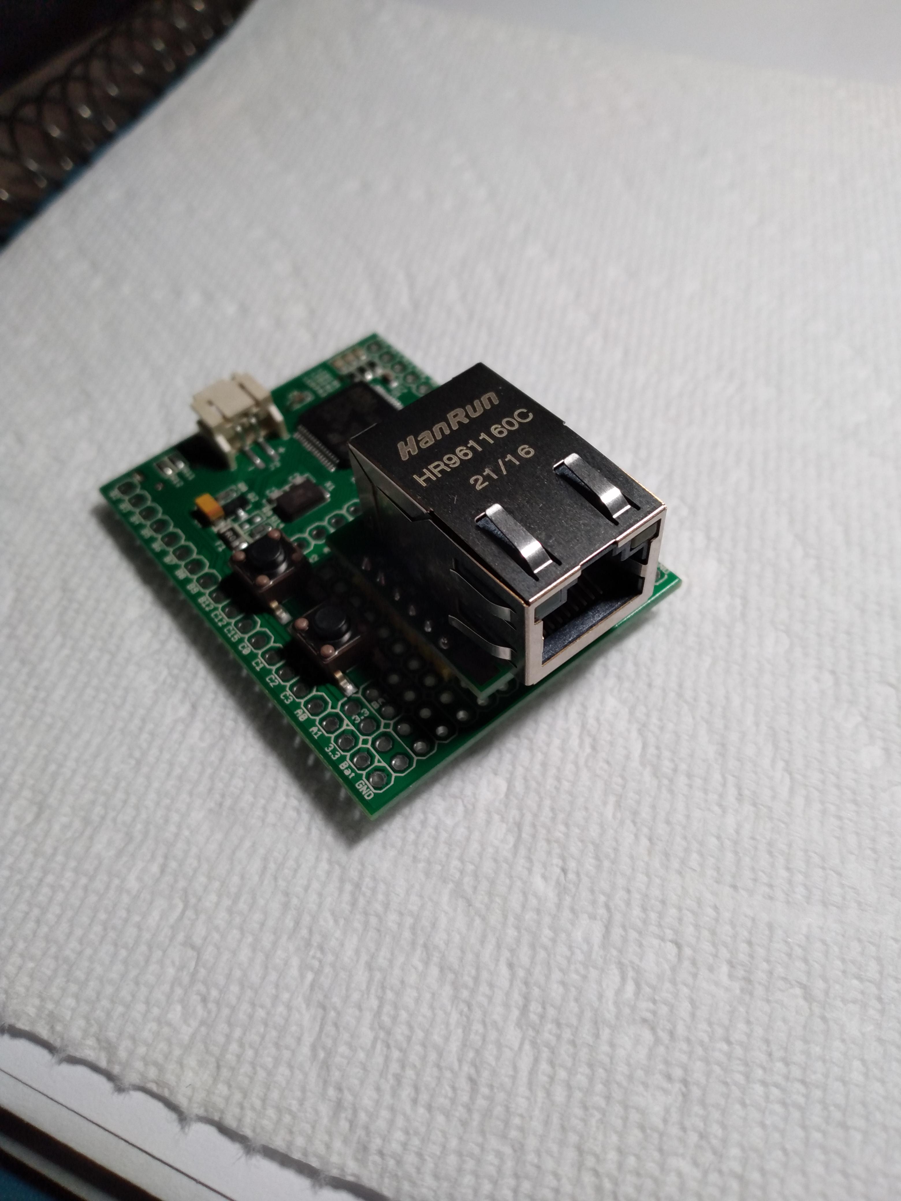
Any reason I can't put a W5500 in the SMD prototype area? I'm fairly new to my own wiring, so I wouldn't mind some experts giving me the thumbs up...
3 Attachments
-
• #7
It all depends on the layout of the pins of the board you want to place onto Espruino.
If the board has two lines of pins falling into the rows of holes of the prototyping area of the Espruino board, it is then just a wiring from the Espruino GPIO pins to those pins.
If the board has a non-fitting pin layout, you need a little adapter board in between for the wiring of the different pin layouts. At that point you may even consider forgetting the prototyping area and go for an adapter board going directly to the GPIO pins of the Espruino board.
What I did - years ago (see http://forum.espruino.com/conversations/127039/#comment5875744, http://forum.espruino.com/conversations/257994/#comment11937364) - was to put machined sockets into the Espruino board holes to have the most flexibility... You can populate just the prototyping area this way and do regular pins on the edge of the board... then you can plug and play using breadboards AND plug-on boards of your choice.
For the (signal) wiring I use enamelled copper with enamel that is heat sensitive and 'burns' away when soldering. I did that for the Pico - with the 1/20 inch pins - and with another Espruino original board - with the pins 'inside' (not on the edge) of the board (A2..A7, B0, B1, B10, B11, and others) and wired them to pins in line with the edge of the board on a separate prototyping board. The prototyping board is a plain thru holes contacted board that I cut to size (for Pico see: http://forum.espruino.com/conversations/327031/#comment14473842). The wiring is on the under side.
In addition to put pin sockets onto the board, I also put plain pins in... the requires a bit filing of the parts of the sockets and pins to fit into the same hole.
-
• #8
Robust answer, thank you! All the pins fit fine in the prototype area, just wanted to make sure that I didn't accidentally put one in a hole tied to some distant pin! I've seen your images, really clever! But in the pictures above, I just have a handful of (standard) pins and I should only have to solder wire to about six of them. I guess there's only one way to prove it out... ;-)
-
• #9
No issue what so ever: the double row of 0.1" holes left and right of the surface mount pads are just connecting to the pads and nothing else. - Indeed: I guess there's only one way to prove it out... and go for it.
-
• #10
Just for any who are interested... it does work! Of course, that's what it's intended for but I'm always concerned I'll fry something.
And for anyone searching, the W5500 Lite module (shown above) has different pin arrangements than the Wiznet board, so it's a little different than the Espruino doc but easy enough to follow. For the Espruino original, connect:
W5500 Lite 	Espruino
J2	G		GND
J2	V		3.3
J2	MI		B4
J1	MO		B5
J1	SCK		B3
J1	CS		B2
Thanks to the Espruino team for making all those modules (ethernet, SD reader). Makes it so easy to get started!
-
• #11
That's great - thanks for letting us know! That's a really tidy little setup!
 allObjects
 Gordon
 DrAzzy
 yngv126399


 @BootySnorkeler
Hi,
I want to know what components are best for the smd prototype area.
Except for motor drivers and transistor arrays, what else can i stick on?
like, flash memory, wifi, radio...
can someone give me the names some really useful add-ons?
EDIT:
Is there a wifi module (preferable esp8266) that has breadboard compatible pins? I would really like to add a wifi module to my espruino board.