-
• #2
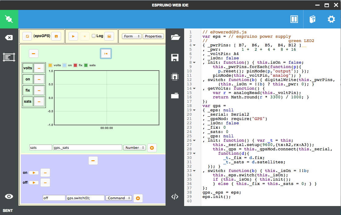
For control UI and visualization of the behavior I used Espruino IDE's built-in and enabled Testing facility with a sampling rate of 2 samples / sec.
I defined the values to plot:
1. volts  - eps.getVolts()
2. on     - (eps._isOn) ? 1 : 0
3. fix    - gps._fix
4. sats   - gps._sats
I defined the switch on and off commands:
1. on   - gps.switch(1);
1. off  - gps.switch(0);
A convenient click on command buttons switches the GPS on and off.
4 Attachments
-
• #3
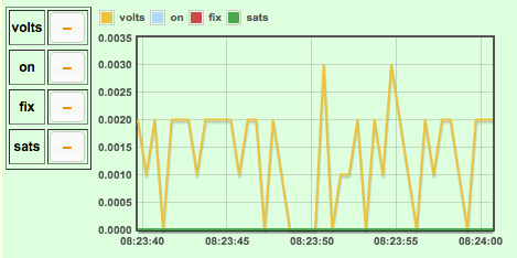
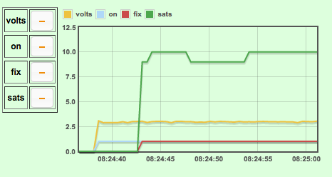
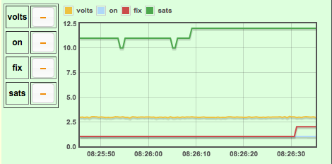
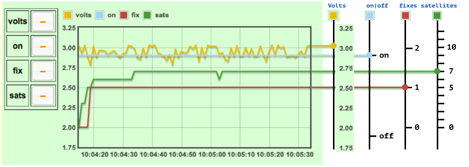
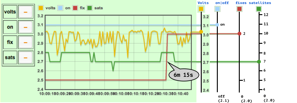
To see more details in the graphs, sampling rate was changed to 1 sample / second, and values offset and scaled (except Volts):
- Volts - light brown line: to scale
- Satellites - green line: 2.0 + 0.1 * sats (0 satellites base line at 2.0, 5 sats at 2.5, 10 at 3.0)
- GPS on - light blue line: on @ 2.9 (in 1st pic) and @ 3.1 (in 2nd pic), off @ 2.1 (off-pic)
- Fix - dark red: 2.0 + 0.5 * fix (0 fix base line at 2.0, 1 fix at 2.5 and 2 fixes at 3.0).
Power 'jumps around between 2.75..3.05 Volts. The longer the switched-off phase is, the slower satellites show. After a short - but still several minutes - break, many satellites are found quickly (5..6). Current was measured with a simple digital multi-meter at an average of 30 mA...
On a 'really cold' start it took a while to get to level of fix = 1 even though some satellites were already found; and it takes quite a while to get to level of fix = 2, even though about the same number of satellites were detected much earlier. I did not look yet after what time the long and lat values become stable and useful. It could be worth-while to look into more recent generations of GPS modules that are much faster - not only in the interval of delivering sentences but also in start-up. A NEO 7M is still waiting on my desk to be 'broken in'. 7M does not only find 20..30% more satellites and quicker, it is more accurate, and has also an extended supply voltage range: Vcc 1.65..3.6V (vs 2.7..3.6V of 6M). The extended supply voltage may require to sacrifice less GPIO pins for just power supply. ;). How much current (mA) an STM32 pins can source is specified based on the voltage drop from Vcc...
Note: The lower number of satellites found in this session compared to earlier session - 7..8 vs 9..12 - was due to a less optimal position of the GPS towards the open sky...
2 Attachments
- Volts - light brown line: to scale
-
• #4
Nice! Great write up. Should it moved to tutorials section?
-
• #5
Update:
I modified hardware and software to provide more details:
- Added a sense/shunt resistor on the high side and the load circuit (in series with the GPS).
- Measure/plot voltage v0 across sense resistor AND load (GPS)
- Measure/plot voltage v1 across the load only (GPS)
Calculate/plot current from delta v0 and v1 and kown resistor value
// ePoweredGPS.js
var eps = // espruino power supply
//                               green LED2
{ _pwrPins: [ B7,  B6,  B5,  B4, B12 ]
, _pwr:        1 +  2 +  4 +  8 + 16
, _volt0Pin: A4, _volt1Pin: A1
, _v0: 0, _v1: 0, _a: 0
, _isOn: false
, init: function() { this.isOn = false;
this._pwrPins.forEach(function(p){
  p.reset(); pinMode(p,"output"); });
pinMode(this._volt0Pin,"analog");
pinMode(this._volt1Pin,"analog"); }
, switch: function(b) { digitalWrite(this._pwrPins,
  (this._isOn = !!b) ? this._pwr: 0); }
, getAmps: function() {
var s0=0.0,s1=0.0,i,iMx=10;
for (i = 0; i < iMx; i++) {
  s0 += analogRead(this._volt0Pin) * 3.3;
  s1 += analogRead(this._volt1Pin) * 3.3; }
this._v0 = Math.round(s0 / iMx * 1000) / 1000;
this._v1 = Math.round(s1 / iMx * 1000) / 1000;
this._a = (this._v1 - this._v0) / 0.47;
return this._a; }
};
var gps =
{ _eps: null
, _serial: Serial2
, _gpsMod: require("GPS")
, _isOn: false
, _fix: 0, _sats: 0, _lat: 0, _lon: 0, _pos: ""
, _gps: null
, init: function() { var _t = this;
this._serial.setup(9600,{tx:A2,rx:A3});
this._gps = this._gpsMod.connect(this._serial,
  function(d){
    _t._fix = d.fix;
    _t._sats = d.satellites;
    _t._lat = d.lat + 10; _t._lon = d.lon - 10;
    _t._pos = "" + _t._lat + "|" + _t._lon;
}); this._init(); }
, _init: function() {
this._fix = this._sats = 0;
this._lat = this._lon = NaN; this._pos = ""; }
, switch: function(b) { if (this._isOn !== (b=!!b)) {
this._eps.switch(this._isOn = b);
if (b) this.init(); else this._init(); } }
};
gps._eps = eps;
eps.init();
// setBusyIndicator(LED1);
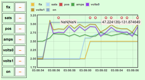
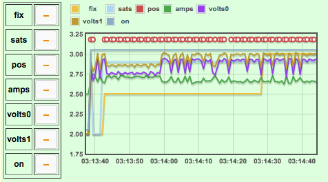
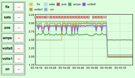
To get higher resolution in the plot, values are scaled and cut off where needed to fit into the y-range of 2..3.1 in the graph and show best resolution/most details:
- fix (light brown) 0 shows as 2, 1 shows as 2.5, and 2 shows as 3 (2 + .5 * fix)
- sats/satellites (light blue): 0 shows as 2, 1 as 2.1, 2 as 2.2, etc (2 + .1 * sats)
- position "lat|long" available (red): show as text on hover over red circles
- current (green): 0 shows as 2.5, then to scale (*)
- volts 0 and 1 (purple and brown): less than 2 show 2, >=2 show to scale
- on/off indicator (teal): off shows as 2.05, on shows as 3.05
*) Calculated current - measured voltage difference over sense/shunt resistor of known value - feels weird: almost 180..250 mA = which it cannot be for sure, last but not least I was measuring the other day around 30 mA.
The sense/shunt resistor is 5 band coded and shows 0.47 R... measured with the digital multi-meter it shows 1.0 R... and in series with a 3.6 R it contributes with 0.4 R. I assume in these low ranges the values are not especially accurate, even though the resistor is a precision (sense) resistor out of a digital power inverter. In other words - for what the (green) amps line is worth - the (green) amps line shows change/increase/decrease of power drawn, and not absolute value. The more noteworthy is the fluctuation of voltage due to power draw and light-weight implemented sourcing... Current has smooth phases and bumpy phases - don't know why. The 0.05 V above 2.7 min Vcc of GPS module is fine but a fine line.
The graph shots include:
- Start-up to fix level 1 (light brown from 2 to 2.5 (0 to 1)
- Start-up all the way to fix level 2: from 2 to 2.5 to 3 (0 to 1 to 2)
- Shut-down.
3 Attachments
- Added a sense/shunt resistor on the high side and the load circuit (in series with the GPS).
 allObjects
 Wilberforce
For loggers over longer periods, the power consumption - more precisely: waste - of the (sensor) peripherals becomes a great issue...
For example: I want to have a GPS logger. The GPS module - for example, u-blox NEO 6 M - draws on start-up up to 67 mA, on average 47 mA, and in power-save mode STILL 11 mA... To survive a decent logging period, the GPS module has to be shut down completely, which means: de-powered.
There are various options, of which the most efficient one is to use a MOSFET as switch. But there are also 'cheap' alternatives, of which one is using Espruino pin(s) to power the device. With suitable staging of power ahead of reading and writing to the peripheral, Espruino can go to sleep again and wait until the device has stabilized, or in case of the GPS, has acquired enough satellites (fix 1 or 2), before even considering processing data.
Since an Espruino (STM32) pin can source up to 20 mA per pin and a 150 [mA] total per chip (EDIT on 2019-20-13: pin 25[ma], 120[ma] pins total, 160[ma] chip total - see this post), I gave it a try with 3 pins: PICO B7, B6, B5 set on "output" and jointly connected to the GPS module's VCC. With A4 I performed the analog read to see what is going on. Unfortunately, the voltage with 3 pins in parallel is not enough. It tanked to 2.5 V on start-up, but 2.7 V are needed, so I added one more pin - B4 - which brought it up just a tad above 2.7 V. Over time - when the GPS module has completed the hard work, it draws less power / current, and the voltage grows to 3.0..3.1 V. This project is a proof of concept. The optimal sequencing and staging of power on and power off for peripheral(s) and Espruino is not implemented yet.
Interesting to this "project" is the fact that Espruio PICO monitores, measures and plots it's own power consumption over time in Espruino's testing feature! (Thank you, @JumJum). For enabling and using this feature see Espruino Web IDE settings and watch some "Youtube's". You will enjoy!
Wiring:
Code:
gps(singleton) object has a.switch(boolean)method to switch GPS on and off for true and false. Switching on and off includes switching on and off its Espruino Power Supplyeps(with same named control method).1 Attachment