-

That's interesting...... I'm using the ESP8266WiFi module. Do I need to upgrade the ESP8266 and run the ESP8266WiFi_0v25 module?
-
Made everything again and am getting the 0x6d00 with the 0x256a now. What does the public key type mismatch mean exactly? Online it says that the client key is not matching the server key (google)? Even tried running your original codes and got the same.....
-
Yeah sorry about that Gordon. I am using the Pico + ESP8266 with pretty much the same code. I am actually working on doing a GET request. 0x256a and 0x7200 is where I am at right now. I did everything as stated in that HTTPS Authorized Certs with Node.js. I've tried changing a few of the codes around. In the Espruino I put the key to client1-key.pem, cert to client1-crt.pem, and ca to ca-crt.pem.
-
So I built my own certificates and am getting these same codes. Nothing with the memory but the 0x2560 and 0x6d00.......
-
Scratch that..... Im getting closer. Now im getting
Loading the CA root certificate... Loading the Client certificate... Loading the Client Key... Performing the SSL/TLS handshake... ERROR: Failed! mbedtls_ssl_handshake returned -0x7200 -
@electronicsguy sounds like your wanting a confirmation returned back to the espruino? HTTPS is your best bet. I'm working to get that up and running right now. I haven't done anything with this for a while as I've been waiting for the HTTPS. Its here, YAY!
@Gordon what do you make of this?
Connecting with TLS... Loading the CA root certificate... ERROR: HTTPS init failed! mbedtls_x509_crt_parse of 'ca': -0x2362 ERROR: Unable to create socket -
Does anyone else use a Chromebook and have issues with the Web IDE not loading modules from the internet? I keep getting an error for the SD card indicating that it does not think its connected with the internet.......
-
Wasn't sure just curious, little over my head at this point
-
Just throwing this out there..... is this possible on the nrf24l01+??
-
Yeah I am pretty sure I was throwing it too much juice. I also received my oscilloscope the other day. It will take me a little time to figure it (oscilloscope) all out but ill do a little testing soon and fill you in.
-
Sorry for not getting back, I've been onto other projects recently. I have received my new NRF modules though :) I should have a board put together in the next day or so and ill update you.
-
Maybe its my chip? Check this out.....
>nrf.sendCommand("1+2", function(r) { print("=="+r); });
=true
>nrf.sendCommbnd("1+2", function(r) { print("=="+r); }); //here I used the up arrow
=undefined
Uncaught Error: Function "sendCommbnd" not found!
 at line 1 col 5
nrf.sendCommbnd("1+2", function(r) { print("=="+r); });
     ^
>nrf.sendCommand("1+2", function(r) { print("=="+r); }); //here I copy and pasted the code manually
=true
Notice when I use the up arrow to reuse the previous code that it changes letter a to b.....
That is weird as I have been able to duplicate it on a few units. The nrf wouldn't have anything to do with this?? Mine has a different pinout-- Waveshare styleand sometimes that 'print("=="+r)' will be replaced with 'print("=="+s)' then 'print("=="+t)' when I use the up arrows to reuse the code....... I'll do some more testing
-
Not sure if this is to do with the update as I had not used the NRF24L01+ before. But when I call it from the PICO as in the example it errors back with "masterHbndler" not found.
SPI1.setup({sck:A5, miso:A6, mosi:A7});
var nrf = require("NRF24L01P").connect( SPI1, B10, B1 );
function onInit() {
  nrf.init([0,0,0,0,2], [0,0,0,0,1]);
}
onInit();
setInterval(function() {
  nrf.masterHandler();
}, 50);
returns
in function called from system
Uncaught Error: Function "masterHbndler" not found!
 at line 1 col 6
{nrf.masterHbndler();}
      ^
BUT when I run the code like this....
SPI1.setup({sck:A5, miso:A6, mosi:A7});
var nrf = require("NRF24L01P").connect( SPI1, B10, B1 );
function onInit() {
  nrf.init([0,0,0,0,2], [0,0,0,0,1]);
}
onInit();
function interval(){
  nrf.masterHandler();
}
setInterval(interval, 50);
it works........
-
YES Got it to work. I actually some how had mixed up the capacitor and the diode...woops... and I also found that the voltage must come from the VBAT.
-
Everything was fine with the Espruino. I built this. The voltage is now at 3.3 volts but it still causes my chromebook to freeze up. On the windows screen still cant seem to make it work properly. I might abandon this barcode scanner for now.
-
Siting idle the tx to ground is 8.6mV and the rx to ground is -7.53 V. The wall adapter powering the barcode scanner is a 5V @ 300mA
-
Voltage is 7.54 volts between the RX and TX.
-
So I used the configuration Manager for the ms146 and everything checks out. A few observations though. On my Chromebook computer once the ms is plugged in through the PICO the computer become unusable. The mouse pad no longer works and random things happen to the screen (programs will close etc.). So I've been forced to use the windows computer which does not have the same issue but it did have to restart randomly. (not 100% sure this caused it) There is a test pad with the config manager and again everything seems to check out.
-
Ill do a little studying up on that Uint8Array. Thanks for the info!
-
Working on integrating a tool box for the work place that will provide some accountability to the user of the tool. The idea is to use the PICO, a MS146-2G Slot Reader (ID cards), a few magnetic holds and slew of TI CD4021BE. The drawers or cabinets will be locked by the magnetic holds, a user will use his ID card to gain access and remove tools from the drawer. Once closed the PICO will scan through and note what tools were removed. I plan to upload the information to a google spreadsheet with the ESP8266 of which I will build some code to send a text reminder to the users to return the tools at the end of the day. Here is the test code for the CD4021 so far.
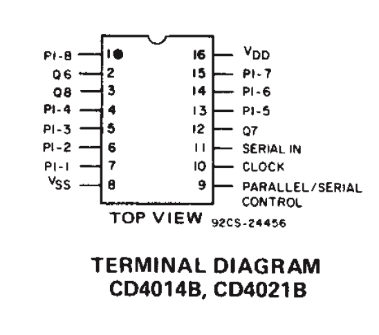
SPI1.setup({sck:A5,miso:A6,baud:9500});//pins 10, 3 respectively function loop(){ digitalWrite(B1,1); // to pin 9 on chip, this allows the chip to collect its data for 20 milliseconds setTimeout(function(){ digitalWrite(B1,0); // turn pin 9 off then........ console.log("register 1 is "+(SPI1.send([0x00])>>>0).toString(2)); //collect data from first chip //I am not 100% on the 0x00 because I've tried other values and it still returns the same. console.log("register 2 is "+(SPI1.send([0x00])>>>0).toString(2)); //collect data from second chip },20); } setInterval(loop,1000);if CD4021 gpio 1 is on return 1, if gpio 2 is on returns 10, 3-->100, all three on returns 111, etc.
Here is a diagram of how the chips are put together. Thanks to the work of the people at arduino.cc was I able to get this part together as some of this would be way over my head. Ill try to get some pictures on here as the project progresses. Thanks
-
DrAzzy:
Unit is powered by it's own power plug in. rs232 pins 2,3,5 and connected to espruino. (rx,tx,gnd). I have tried switching the rx and tx and then nothing will produce.
="ææææf&æÌfææ¦Ö\x00"
=new Uint8Array([230, 230, 230, 230, 102, 38, 230, 204, 153, 102, 230, 230, 166, 214, 0])
And I don't have an Ocilloscope but have a good excuse to get one now.
-
I am trying to connect a bar code scanner to my PICO.
Serial2.setup(9600, {rx:A3,tx:A2,bytesize:8,parity:none,stopbits:1,flow:none}); Serial2.on('data', function(data) { console.log(data); });The response I am getting is gibberish though?
þ
æ
æ
æ
æ
f
&
æÌ
f
ææ
¦
Ö
I have tried various other baud rates and nothing seems to work. The code should read 0000027840200.
Any ideas?? -
Any idea as to why the slower baud was cause issues where the higher works fine? Is anyone else able to confirm what I am seeing?
-
Just a little FYI. I found that changing the original ESP8266 (ESP8266_AT_V00180902_04.bin) Baud Rate to 115200 made it much more reliable. Serial2.write("AT+CIOBAUD=115200")
Espruino
Espruino is a JavaScript interpreter for low-power Microcontrollers. This site is both a support community for Espruino and a place to share what you are working on.
Ugh this is getting frustrating. I updated the esp. I copy and pasted your code from GitHub and only changed the wifi settings.