-
-

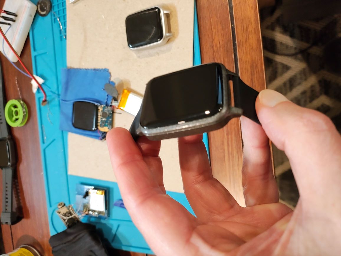
That's right. Co-fit according to the manual. I tried getting a firmware update for reversing, but it's "up to date". I also contacted seller to see if I could get a firmware update sent to me. Nope.
As it is, it's quite usable. The GPS, temperature and HRS is a matter of time and effort. I could use help ;-) -

Not Magic/Rock board, it's totally different, different pins all around. (https://github.com/yngv27/EWatches/tree/main/TK87G).
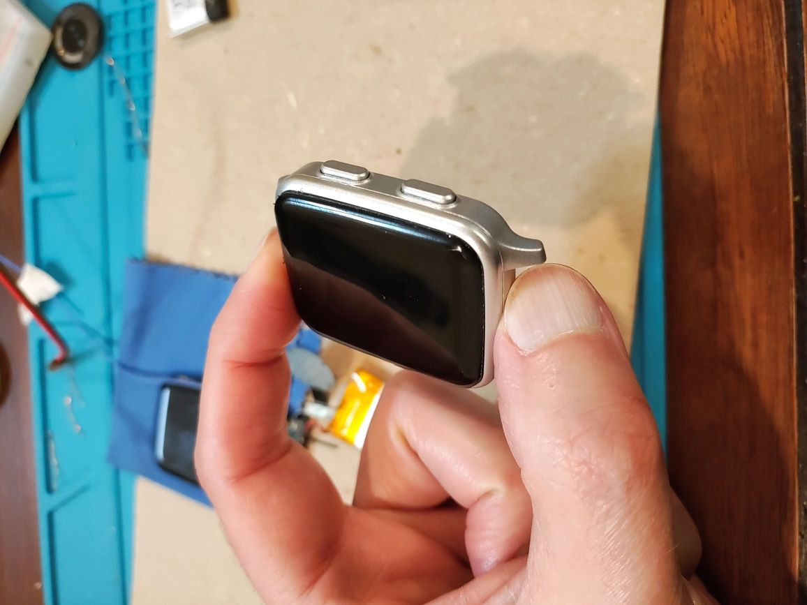
Screen is ST7789 240x280, very nice, I'd say it was Rock like. Don't know if touch is auto-sleep, I just put it to sleep on screen sleep (I adopted @jeffmer 's wOS object). It's light weight, like the (ironically named) Rock, much lighter than the Magic3. -

I've kept my work on other watches relatively quiet, as I didn't want to steer anyone away from supporting Gordon monetarily. I think everyone should buy some kind of Espruino hardware to keep the proverbial lights on.
I feel fortunate to have learned enough from folks here HOW to build Espruino for various watches (all nRF52), and for me, the fun is in the discovery of the hardware internals. Like @fanoush I don't wear any of these hacks.But since much of the cat has left the bag....
I'm working with two others right now:
P4: https://www.aliexpress.com/item/1005007150275911.html - 52832, but DaFit so hackable without opening. It seems to be having power issues (likely needs some pin pulled up/down - not sure). Classic DaFit: shared SPI for LCD and Flash, for which I use @jeffmer 's build to manage. This is something neither Bangle had to contend with, so it was the efforts of folks here who made that happen.
TK78G: https://www.aliexpress.com/item/1005008054139256.html (and above from @enaon )
52840 with tons of goodies like GPS, temperature, HRS, accel, two buttons and touchscreen. I've got the touchscreen working 100%, accelerometer usable (don't know what it is, so not sure what options I can set like changing sensitivity/power settings). I have been trying to figure out the GPS, as I know what pins are being used, but I can seem to turn it on. But if you want to explore, and learn, this is a good one to work with!
And as mentioned above: Pinetime (https://pine64.com/product/pinetime-smartwatch-sealed/) very similar to P8 and very well documented. New ones arrived sealed, which makes things a bit more tricky.. it takes a bit of effort to put the correct bootloader on this for updating to Espruino.But the only way you'll get a full support watch is Bangle2. Everything else is "roll up your sleeves", and quite a bit of swearing.
-
-

Anyway, it may be a feature https://github.com/espruino/Espruino/blob/master/targets/nrf5x_dfu/main.c#L145 , not bug.
That's if you don't define a BTN1. Even so, the comment says it should exit DFU after a few seconds and boot properly... which is why I thought maybe I didn't have the right entry point defined somewhere?
-

I did define a BTN1 for this watch, but as I said, not sure if the fact that it's normally closed and had to invert it in software was any issue. I assume that magic happens at a lower level than the DFU main.c? I'll try the define above, since now the battery seems to be depleting overnight so I'm upgrading it regularly ;-)
BTW: the screen is a GC9A01, just like DICKENS, however it doesn't seem to display anything on cold boot despite my defining the pins in the board file. Nor does it buzz which I believe my Bangle does due to board definition? -

I have just put Espruino (2v24) on a smartwatch that has an nRF52832 on board. I determined the button GPIO and created a board file for it, that all works well. If I issue an E.reboot(), everything is fine, comes back to Espruino. Also if the Watchdog gets tripped, it boots to Espruino. If I let the battery run down to cold and plug it in however it jumps to DFU and stays there. I have to reload Espruino each time. I'll enclose the board file below. I've had issues with getting to DFU at all from other boards/watches I've worked on, this is the first time I've experienced this.
Notes: BTN1 (D28) is normally high, goes low when pressed, so I inverted it in the board file. I gathered that the IN_PULLDOWN works opposite when inverted as the pin needed to be pulled high to properly register. Works as expected when running (normally low, pressing sends it high).
Also: originally I did a full build (RELEASE=1 BOARD=M98) and used SWD to program the entire package (so it received SD, firmware, bootloader, MBR and UICR). The current UICR is all "ffffffff" except:
0x10001014: 0x78000
0x10001018: 0x7e000
Any ideas very much appreciated... -
-
-

I have it running now: display, buttons, led, backlight. But spi flash is not behaving (I have had this issue with a few other SPI flashes on watches). Builds OK, Storage seems to accept writes, but when you go to read, the files soon disappear. I've tried with build DEFINE for explicit sleep/wake, doesn't help.
-

@fanoush Seems like you got pretty far with the pixl version. I've just received one with the LCD and I'd like to pursue getting the screen going. Have you made a board file for it you can share? I've never used NFC before so I'm not sure how to enable it (other than making sure D9/D10 are NOT built as regular GPIOs).
-

One crucial recommendation is to avoid setting payment terms on a monthly or yearly basis, as this scares people away. Instead, consider offering lifetime or per-project licenses, which are generally more acceptable.
For individuals, I agree. For commercial, this is an accepted way of maintaining an active and useful tool. So if he does go with a commercial license of some kind, this seems viable to me.
-
-

I am running a custom Espruino and am trying to have it display incoming texts. I have a GB() function for it, and when I run the GadgetBridge debug utilities, they seem to work just fine, but when I receive a text, my GB() function is not called. Am I missing a setting? I set all the permissions it asked for when I installed GB. Any help appreciated...
jv -

@fanoush Two years later and you're still making my day... I've had trouble getting my STlink working with OpenOCD and just wanted to write a quick/dirty SWD app in Espruino. Not only have you already done that, but you made my STlink useful! Once I get the SWD app working, I'm going to write an HTML front-end to upload firmware via the dongle.
Turns out I have the APM32 version. I tried the CMSIS-DAP binary but that didn't work (haven't gotten it to work on my DAPlink either!) But I'm charged now, so thanks for the work! -

https://www.aliexpress.com/item/1005002480008305.html
I see "That product can't be shipped to your address" -

https://www.aliexpress.com/item/1005004728587963.html
The board is easy to solder too, plus you get two buttons.I should add: I removed the original SQUARE display as it was cracked on delivery; that leaves the entire 12-pin array of solder points so if you can solder at 0.6mm you can get 3.3,GND,and 5 GPIOs (for the display CS,RST,SDA,SCL,DC). These are tricky and fragile solder points so I just used two here and secured them
-
-

I found 3 pads on the back that were not listed on @fanoush's Magic3 pin table: D13 (unmarked, grouped with SXD,TXD,D+,D-), D28 (unmarked, to the far right of that cluster), and D27 (unmarked, to the near right, below and to the left of D28). I also reused I2C SDA/SCL as I have removed the touchscreen. Of course, that's the ACCEL lines as well, so you'd have to write a cooperative routine that makes sure they don't interfere with each other.
Also good for hacking is the DT28 (also cheap on AE). No "new" pins that I found, but you can find the touchscreen pads (SDA,SCL,INT,RST). When I get a chance I can check the RX/TX to see what they are...
-

@fanoush Lots of things to try, thank you. So far, it's still going (nearly 2 days now) so that's a good sign that it was simply the SPI flash not sleeping. But if I do choose to use it, I'll have to know some of these tricks.
-

totally agree I don't know why they share those lines.. and this one actually shares data and clock with display, SPI flash AND accelerometer! However, as I've removed the display and the touchscreen, I've grabbed the touchscreen SDA/SCL for my e-ink display, so that's not shared.
However, I'm not initializing the accelerometer at all, so I'm hoping it's not doing anything (yet). My intention was to use a very basic JS driver and simply ignore any requests if the SPI flash is low. Klunky, but it should do for now.
Right now the watch has been running off charger for 19hours, but NRF.getBattery() is reporting 3.02 so not expecting it to last the night... this is with manually setting the SPI flash to sleep (current firmware isn't using it for Storage, but it is compiled in so I can get it via require("Flash"))
-
-

I have Espruino running on a DT28 smartwatch (NRF52832) with its display removed. I've soldered wires to the main board to run an e-ink display, which works fine. The watch has an 8MB SPI flash chip which I've compiled in and it works, but with power issues. My first pass I was getting nothing back with every first call (call .list() get nothing, call it again, get file list). This sounded like it needed to be woken up, so I added the flag
'DEFINES += -DSPIFLASH_SLEEP_CMD', # SPI flash needs to be explicitly slept and woken upand it that stopped the errors, but now my battery dies in about 2 days (as opposed to 10 days without flash at all). I don't have an easy way to measure the power draw other than battery life (a 200mAh which I charger for 2 hours).BTW: SPI flash shares NO GPIOs with the display. It DOES share CLK/DATA with the accelerometer, but I do not initialize or use that at all (yet).
All thoughts appreciated. Board file is
import pinutils;

info = {
 'name' : "DT28 smartwatch",
 'boardname' : 'DT28', # visible in process.env.BOARD
 'default_console' : "EV_BLUETOOTH",
 'variables' : 2565,
 'bootloader' : 1,
 'binary_name' : 'e_%v_dt28.hex',
 'build' : {
   'optimizeflags' : '-Os',
   'libraries' : [
     'BLUETOOTH',
     'GRAPHICS',
     'JIT',
   ],
   'makefile' : [
 'DEFINES+=-DCONFIG_GPIO_AS_PINRESET', # Allow the display MOSI pin to work
     'DEFINES += -DCONFIG_NFCT_PINS_AS_GPIOS',
     'DEFINES+=-DNRF_BLE_GATT_MAX_MTU_SIZE=53 -DNRF_BLE_MAX_MTU_SIZE=53', # increase MTU from default of 23
     'DEFINES+=-DUSE_FONT_6X8',
     'DEFINES += -DSPIFLASH_SLEEP_CMD', # SPI flash needs to be explicitly slept and woken up
     'DEFINES+=-DBLE_HIDS_ENABLED=1 -DBLUETOOTH_NAME_PREFIX=\'"DT28"\'',
     'DFU_PRIVATE_KEY=targets/nrf5x_dfu/dfu_private_key.pem',
     'NRF_BL_DFU_INSECURE=1',
     'DFU_SETTINGS=--application-version 0xff --hw-version 52 --sd-req 0x8C,0x91',
     'INCLUDE += -I$(ROOT)/libs/misc',c'
   ]
 }
};


save_code_pages = 20;
chip = {
  'part' : "NRF52832",
  'family' : "NRF52",
  'package' : "QFN48",
  'ram' : 64,
 'flash' : 512,
  'speed' : 64,
  'usart' : 1,
  'spi' : 1,
  'i2c' : 1,
  'adc' : 1,
  'dac' : 0,
  'saved_code' : {
          'page_size' : 4096,
          #'address' : ((118 - save_code_pages) * 4096), # Bootloader at 0xF8000
          #'pages' : save_code_pages,
          'flash_available' : 512 - ((35 + 8 + 2)*4), # Softdevice 5.0  uses 35 pages of flash, bootloader 8, FS 2. Each page is 4 kb.
          'address' : 0x60000000, # put this in external spiflash (see below)
          'pages' : 2048, # 8MB of the 16MB external flash
   },
};


devices = {
 'BTN1' : { 'pin' : 'D29',  'pinstate' : 'IN_PULLDOWN'},
 'BTN2' : { 'pin' : 'D30',  'pinstate' : 'IN_PULLDOWN'},
 'BTN3' : { 'pin' : 'D31'},  # Fake button: bootloader wants THREE

  #'VIBRATE' : { 'pin' : 'D22' }, # Pin negated in software

  #'LCD' : {  # unused for bootloader

 'SPIFLASH' : {
            'pin_sck' : 'D9',
            'pin_mosi' : 'D8',
            'pin_miso' : 'D7',
            'pin_cs' : 'D6',
            'size' : 8192*1024, # 16MB
            'memmap_base' : 0x60000000 # map into the address space (in software)
  }
};

# left-right, or top-bottom order
board = {
  'left' : [ 'VDD', 'VDD', 'RESET', 'VDD','5V','GND','GND','','','D3','D4','D28','D29','D30','D31'],
  'right' : [
     'D27', 'D26', 'D2', 'GND', 'D25','D24','D23', 'D22','D20','D19','',
     'D18','D17','D16','D15','D14','D13','D12','D11','',
     'D10','D9','D8','D7','D6','D5','D21','D1','D0'],
  '_notes' : {
    'D6' : "Serial console RX",
    'D8' : "Serial console TX"
  }
};
board["_css"] = """
[#board](https://forum.espruino.com/search/?q=%23board) {
  width: 528px;
  height: 800px;
  top: 0px;
 left : 200px;
  background-image: url(img/NRF52832DK.jpg);
}
[#boardcontainer](https://forum.espruino.com/search/?q=%23boardcontainer) {
  height: 900px;
}
[#left](https://forum.espruino.com/search/?q=%23left) {
    top: 219px;
    right: 466px;
}
[#right](https://forum.espruino.com/search/?q=%23right) {
    top: 150px;
    left: 466px;
}
.leftpin { height: 17px; }
.rightpin { height: 17px; }
""";

def get_pins():
  pins = pinutils.generate_pins(0,31) # 32 General Purpose I/O Pins.
  pinutils.findpin(pins, "PD2", True)["functions"]["ADC1_IN0"]=0;
  pinutils.findpin(pins, "PD3", True)["functions"]["ADC1_IN1"]=0;
  pinutils.findpin(pins, "PD4", True)["functions"]["ADC1_IN2"]=0;
  pinutils.findpin(pins, "PD5", True)["functions"]["ADC1_IN3"]=0;
  pinutils.findpin(pins, "PD28", True)["functions"]["ADC1_IN4"]=0;
  pinutils.findpin(pins, "PD29", True)["functions"]["ADC1_IN5"]=0;
pinutils.findpin(pins, "PD30", True)["functions"]["ADC1_IN6"]=0;
  pinutils.findpin(pins, "PD31", True)["functions"]["ADC1_IN7"]=0;
  # Make buttons and LEDs negated
  pinutils.findpin(pins, "PD29", True)["functions"]["NEGATED"]=0;
  pinutils.findpin(pins, "PD30", True)["functions"]["NEGATED"]=0;

  # everything is non-5v tolerant
  for pin in pins:
    pin["functions"]["3.3"]=0;
  return pins
Espruino
Espruino is a JavaScript interpreter for low-power Microcontrollers. This site is both a support community for Espruino and a place to share what you are working on.


Anyone having an issue with the Nice!Nano bootloader after updating app to Espruino(app only)? I short RST to GND 2x and it displayed a drive, copied the espruino.uf2 to it, works great! When I try to short the pins again, I see the device reboot, but it doesn't enter bootloader.
??