-
• #2
PWM should do push/pull just fine in normal mode? I have used it with a voltage multiplier in the past without problems.
However PWM freq/duty cycle won't directly affect the voltage out the end - so I guess you'll need a voltage divider and then some kind of feedback loop?
-
• #3
...yeah... have some thinking to do, because the "new ground" will have then an offset if I make the 'ground of the voltage divider' with voltage divider so that the input is kind of a 'real AC'... but then the 'new ground' has an offset and poses challenges for devices 'down the wire'...
-
• #4
Powered the doubler/quadrupler the wrong way... dddoooohhhh...
Now, with correct wiring, I get with n stages and loads:
var c=`

//   n=1    n=2    N=3    n=4    n=5    n=6
// out V  out V  out V  out V  out V  out V  Load R
// -----  -----  -----  -----  -----  -----  ------
//  4.57   5.85   7.07   8.26   9.59  10.80    none
//                       7.77   8.86   9.89    100K
//                       7.57   8.60   9.51     47K
//                       7.47   8.42   9.21     33K
//                       7.31   8.14   8.88     22K
//                       6.86   7.28   7.67     10K

`; // putting in multi line comment to overcome low legibility of forum
This is with this code:
// voltageMultiplier.js
//
// n stages, 10uF and 1N4004 w/ 22uF between out and GND
// w/ 3.3V on C-_D and A8 on C-
//
//   n=1    n=2    N=3    n=4    n=5    n=6
// out V  out V  out V  out V  out V  out V  Load R
// -----  -----  -----  -----  -----  -----  ------
//  4.57   5.85   7.07   8.26   9.59  10.80    none
//                       7.77   8.86   9.89    100K
//                       7.57   8.60   9.51     47K
//                       7.47   8.42   9.21     33K
//                       7.31   8.14   8.88     22K
//                       6.86   7.28   7.67     10K
//

var vMulP  = A8     // voltage Multiplier PWM Pim
  , vFreq  = 4096   // PWM frequency
  , vRVal  = 0.5    // PWM relative value;
  ;

function von() { // voltage on
  pinMode(vMulP,"output");
  analogWrite(vMulP,vRVal,{freq:vFreq});
}

function voff() { // volatage off
  pinMode(vMulP,"input");
}
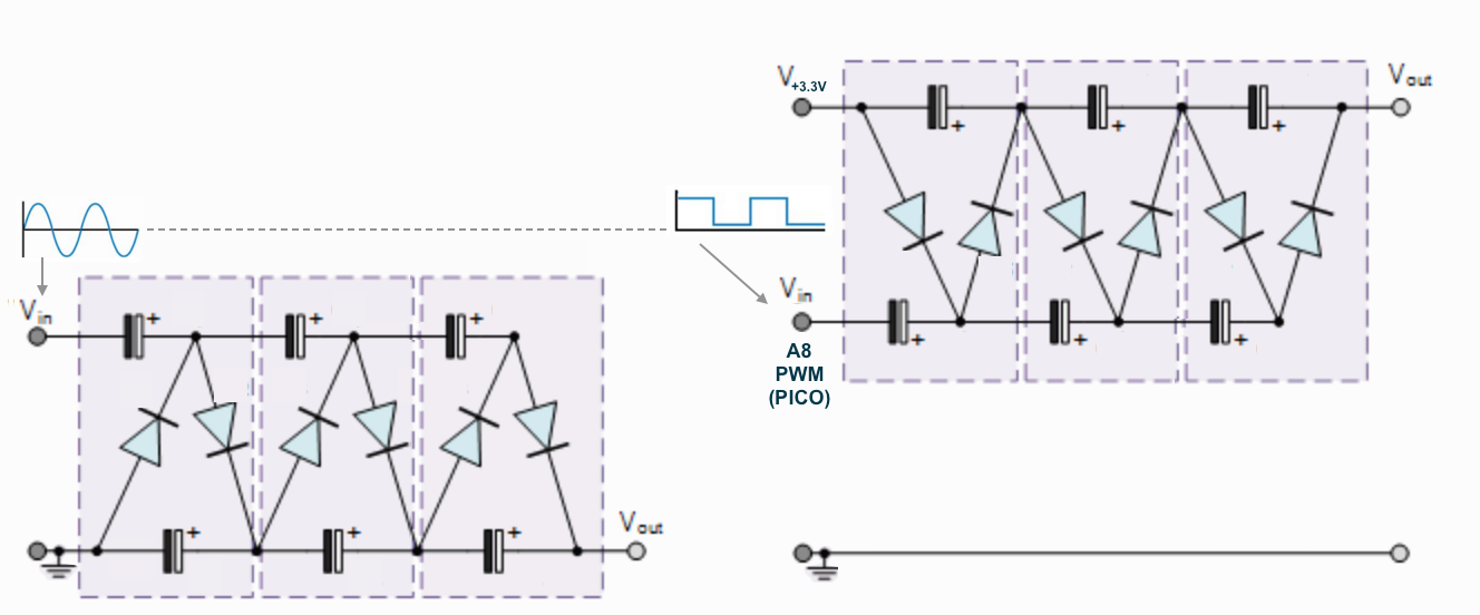
on n stages capacitors-diodes voltage multiplier with 10uF capacitors and 1N4007 diodes on A8 on PWM on a PICO (the pin and PWM I thought I blew in a different conversation...).
4 stages are just a TAD - uppercase - short on the 10V I was looking for. In other words, either the loss is significant or the input is not pushy enough... so I had to add some more stages...
Interestingly was that the lower frequency 4..8KHz fared better than the higher 16..32K. This may be fixed with different capacitors... and may be diodes too...
Because we do not have negative swing like with real AC, the wiring is not as usual: What usually is connected to Ground (GND), has to go to 3.3V... ;-)
1 Attachment
-
• #5
Because we do not have negative swing like with real AC, the wiring is not as usual: What usually is connected to Ground (GND), has to go to 3.3V
Ahh, yes - I've only used voltage multipliers with digital circuits so I never thought to mention that :)
What about using schottky diodes? By getting the diode voltage drop down to 0.3v instead of 1v you could make the voltage multiplier substantially more efficient...
-
• #6
I thought about that after I had to add so many more stages to get 10V. Since this is only the supply of a followup circuit - an non-inverting op amp as dc amplifier with hf=3 - and the results with load look so bleak, I question the setup.
The hint about wiring a non-AC - DC - source to a voltage multiplier I got from article abuyt DC VOLTAGE CONVERTER CIRCUITS of the nutsvolts.com magazine site.
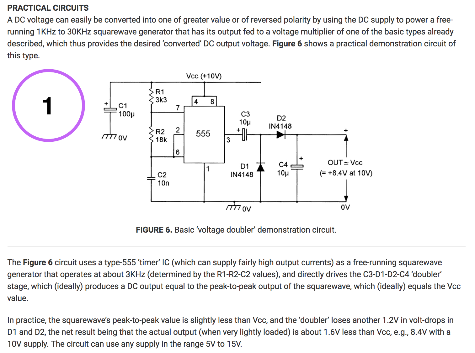
It starts out with a NE555 timer / square wave signal generator driving two stages - figure 6 (see 1st attachment) - but not very effective when looking at the supply voltage... ;-)... though completely explainable: the 'AC full swing' is about 10V 'PEP' - the DC of the supply - which is effectively only about 5V nominal AC and results - with the losses - in 8.4V.
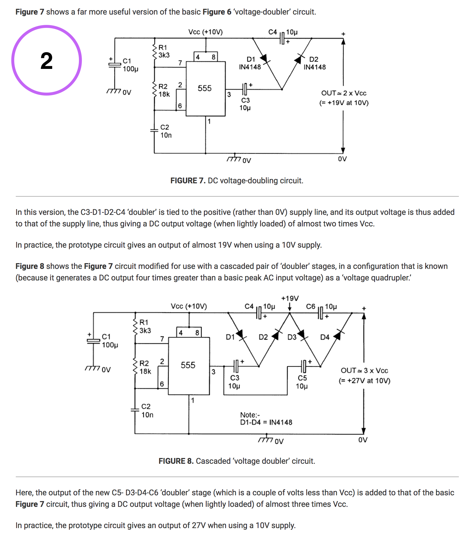
I notice also that in Fig. 8 of this article, the C is 'always' based on the input / DC square wave (see 2nd attachment). I did not try that yet because it could because I don't if it is save, since this is then all connected to the Espruino micro controller pin. If no issue, one could get 'faster' - with less stages and thus less loss to the desired voltages.
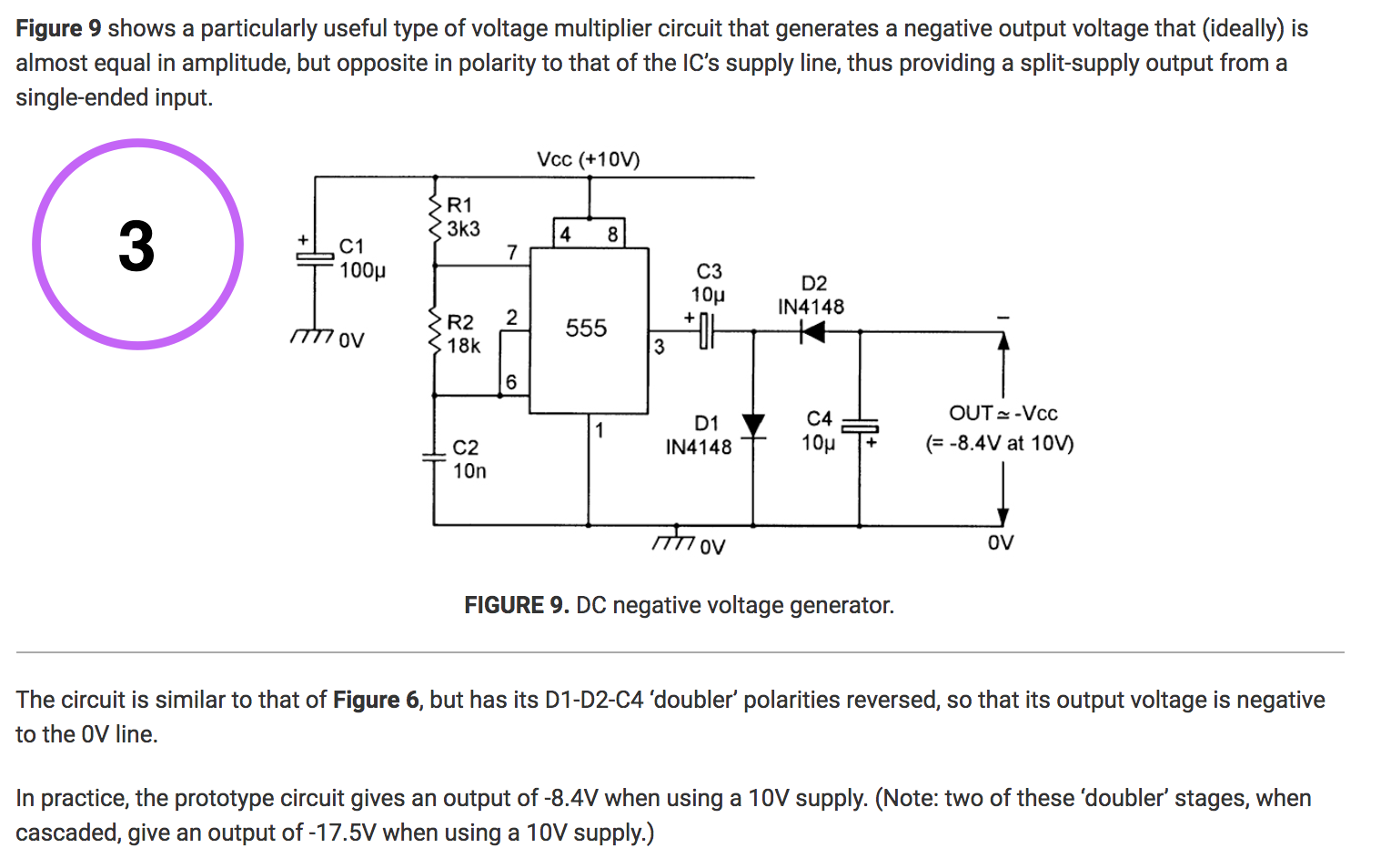
PS: Interesting is that this article in nutsvolts.com online magazine has also a circuitry for creating NEGATIVE voltages: figure 9 (see 3rd attachment)
3 Attachments
 Gordon
 allObjects


I try do drive with a Pico without extra hardware a passive voltage multiplier made w/ Cs and Ds to control a VCO that needs 1..10V to get the full range.
How would I do that?
PWM does not what I need... it only does the push... but not the pull down.... It gives me though access to frequency and duty cycle...
Voltage Multiplier - one of the many: