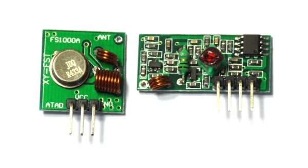
I have the same receiver and transmitter as on this image:
After some tests I found that left one on the image is the transmitter (3 pins) and right one is the receiver (4 pins)
I using the code from example, here are my exact code with connections:
/**
On press button BTN1 send bits (CODE variable) from transmitter (A1) to receiver (A0) multiple times. Blue LED blinking on send data, green LED blinking on receive data.
Transmitter:
GND <-> GND
VCC <-> Bat
ATAD <-> A1
Receiver:
GND <-> GND
VCC <-> 3.3 (If using Bat there are many errors that we get on input)
DATA1 OR DATA2 <-> A0
*/
var t,n, counter = 0;
// When the signal rises, check if it was after ~5ms of delay - if so (and if we have a code) display it.
function sigOn(e) {
// console.log('sigOn:', getTime());
var d = e.time-t;
if (d>0.005 && n>0) {
console.log(counter++, ":0b"+n.toString(2));
n=0;
}
t = e.time;
LED2.write(1);
}
// When the signal falls, measure the length of our pulse.
// If it was within range, record a 1 or a 0 depending on the length.
// If it wasn't in range, zero it
function sigOff(e) {
// console.log('sigOff:', getTime());
var d = e.time-t;
t = e.time;
if (d>0.0001 && d<0.001)
n = (n<<1) | ((d>=0.0004)?1:0);
else
n=0;
LED2.write(0);
}
setWatch(sigOn,A0,{repeat:true,edge:"rising"});
setWatch(sigOff,A0,{repeat:true,edge:"falling"});
var TX = A1;
var CODE = 0b10100000111111101110;
function sendCommand(command) {
LED3. write(1);
var bits = (CODE & ~0b11111) | command;
for (var i=24;i>=0;i--) {
if ((bits>>i)&1) {
digitalPulse(TX,1,0.9);
digitalPulse(TX,0,0.3);
} else {
digitalPulse(TX,1,0.3);
digitalPulse(TX,0,0.9);
}
}
digitalPulse(TX,1,0.001);
LED3. write(0);
}
function sendMultiple(command) {
var n = 9;
var interval = setInterval(function() {
sendCommand(command);
if (n-- < 0) clearInterval(interval);
}, 50);
}
var socketOn = false;
setWatch(function() {
socketOn = !socketOn;
sendMultiple(socketOn ? 0b11110 : 0b01110);
}, BTN1, { repeat:true, edge:"rising", debounce:10 });
// A1 -> transmitter (3 wires) green
// A0 -> receiver (4 wires) yellow
Hope this helps, LMK if you need some help, I passed it before few days. :)
BTW, how did you checked the remote control that it works fine?
PS: Here is additional good explanation for the code if you need it.
Espruino is a JavaScript interpreter for low-power Microcontrollers. This site is both a support community for Espruino and a place to share what you are working on.
I have the same receiver and transmitter as on this image:
After some tests I found that left one on the image is the transmitter (3 pins) and right one is the receiver (4 pins)
I using the code from example, here are my exact code with connections:
Hope this helps, LMK if you need some help, I passed it before few days. :)
BTW, how did you checked the remote control that it works fine?
PS: Here is additional good explanation for the code if you need it.