-
• #52
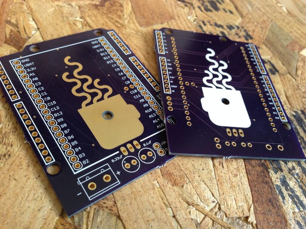
Checkout what just arrived in the post :)
I've already spotted one issue, which is that the terminal block blocks the power (which I wanted) but also prevents you from connecting the USB (doh!). I'll switch it to the other side, but for the time being, might be better connecting some wires than a terminal block.
@Hardware_Hacks do you want to DM me your address (on here or on twitter) and I'll send one out to you.
Matt
1 Attachment
-
• #53
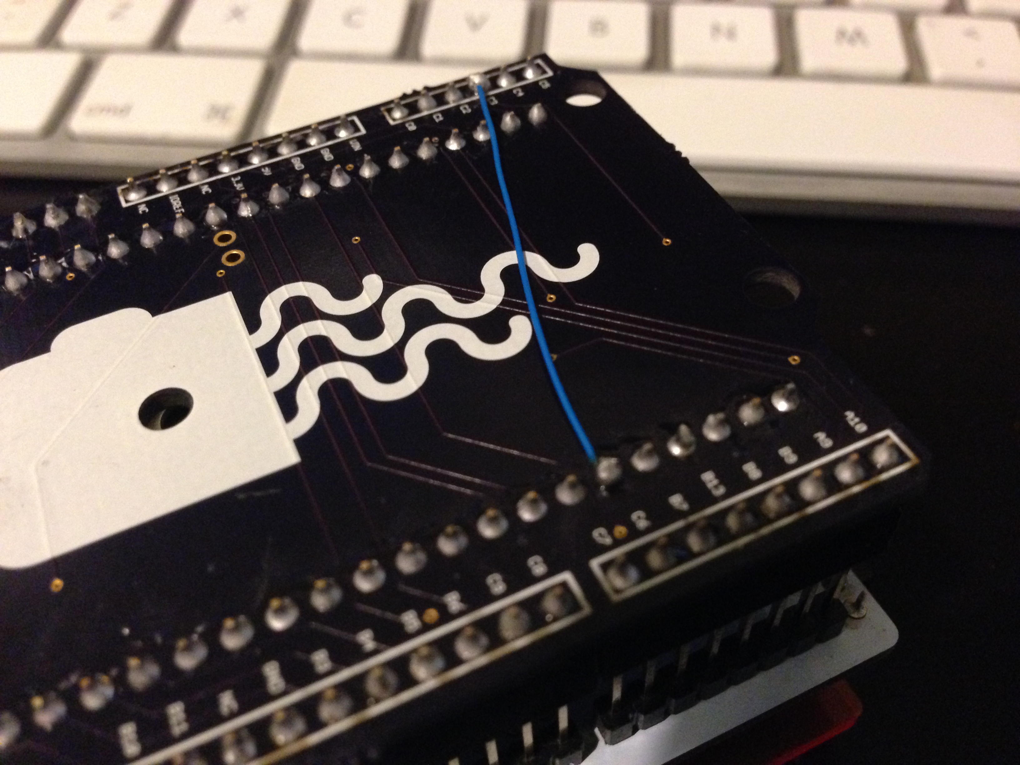
Doh! Looks like I forgot to hook up the C3 pin, temporary fix deployed :)
1 Attachment
-
• #54
Looks great - I see you've got some of the game shield working with it already?
-
• #55
They look excellent I'll DM you once home
-
• #56
@Gordon yea, seems to be working pretty well so far which is cool (though annoyingly I've spotted another un-wired PIN B10, although that's one of the awkward ones in the middle that I doubt people will connect anyway so not a biggy right now)
I've updated my eagle layout though with those two wires now connected, and the terminal block on the other side, so I'm keeping it up to date as I go along.
@Hardware_Hacks I'll keep an eye out :)
-
• #57
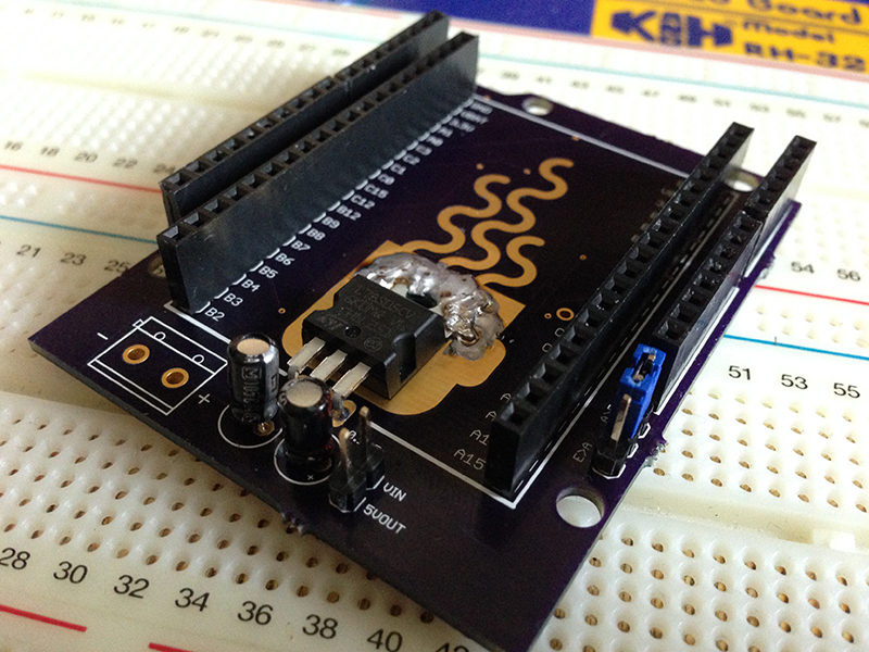
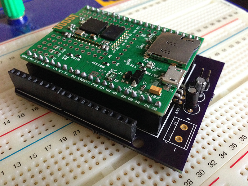
Couple of pictures for you. One of the board soldered up, and one with the Espruino in place.
2 Attachments
-
• #58
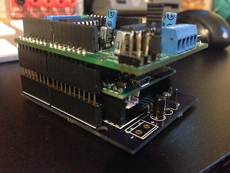
Oh, and for my DIY gamer it's not an issue because it has pretty long legs, but for general shield usage, I'd just say plug a set of stacking headers in the arduino headers (on the adapter) and plug the shield into that.
Like this:
1 Attachment
-
• #59
That board looks great! How expensive was it to have something like that made? I'm going to need some custom boards, and I'd been planning to do it myself (laser printer method)... but something that looked like... like that, would be awesome, if I can cost-justify it.
-
• #60
Three boards of that size from OSHPark (they have a minimum order size of 3) was $28.00. I've not received anything from customs yet so I'm hoping they just got through :)
Another option is ragworm.eu which is in the UK but they are a bit pricer (though probably quicker turn around, OSHPark took about 1 week to print, then 1 week to deliver using their free delivery option).
Matt
-
• #61
Saying that, I see you are in the US, so OSHPark shouldn't be a problem for you.
-
• #62
Hmmmm, that's not too bad, especially since they put the holes in it and everything.
Pity eagle costs a stupid fortune :-/
-
• #63
I made these with the free version. Can't remember what the restriction is. I think it's a max board size so guess it depends on the size of board you need to make.
-
• #64
Oh cool. I must have missed that there's a free version!
-
• #65
Looks great! Really good to see some Arduino shields on it.
IIRC Eagle free maxes out at 2 side, 160x100mm - which is enough for pretty much anything :)
-
• #66
@gordon is it possible to wire up buttons to trigger button 1 / the rest button? With the espruino being upside down, it makes it tricky to push the buttons, so would be good if I could add some custom buttons on the edge to trigger them.
From the reference diagram, it looks like Btn1 is pin B12 is that correct? I couldn't find anything for reset.
Any pointers?
Matt
-
• #67
BTN1 is B12, as I understand it.
Right next to C11, there's a hole on the Espruino where a pin could be installed, and "RST" is silkscreened next to it. I'd wager that that's the reset pin.
-
• #69
Cool! How did I not notice that :)
-
• #70
RST is pull-down IIRC though, and BTN1 is pull-up :)
-
• #72
The other way around I think. When the button is pressed you want to short RST to GND, and BTN1 to 3.3v.
-
• #73
Is that right? My inputs on the DIY Gamer are set to "input_pullup", and they are wired to ground.
-
• #74
Seems you were right (used some jumpers and ran a quick test). I'll update the board accordingly :)
-
• #75
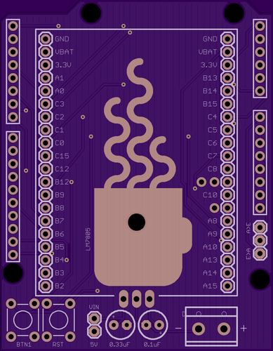
Ok, wadda we think to v2?
I've added buttons, wired up the missing connectors, moved the terminal block to the other side, and made sure both sides of the boards are filled with copper (On the top side, the entire fill is used as the heat sink, I just expose the coffee cup shape to solder onto).
Matt
1 Attachment
 mattbrailsford
 Gordon
 Hardware_Hacks
 DrAzzy
@mattbrailsford thanks, I've just received my replacement Espruino and I've sorted out a few of my arduino shields to run through:
I have a few more but if the above pass then all should be ok. The GSM shield is the one I'm most interested in as its been known to be a pain even when sat on top of a Uno.