-
• #27
Mon 2019.08.12
Hi @pankleks, I recently thought (wrongly) that setWatch() was problematic. Gordon demonstrated a solution with the following snippet:
It is likely that the Javascript needed to process the digitalRead() is the issue. My really rough timing observation is that Espruino needs around 50usec overhead to make the call, and another variable amount to get the rest of the instructions processed. I'm clocking data accurately with 2usec pulse width, 500KHz spaced at tenth second intervals.
Are there any setIntervals() running?
What does the datasheet show for max readings?
Are we Absolutely certain that the interface electronics is as needed and that 'pull down' is the appropriate mode?
Both devices share a common ground?
-
• #28
Mon 2019.08.12
Hey @PeterD, you never cease to surprise us! Another two days and a rough finished proof of concept done towards your project goal.
Curious, did you retain a continuous strip of the WS2811 or are they individual bulbs? Wondered if you are using small 8 element arrays for the individual seqments, and just chaining them together in memory to form the digit? Would you mind sharing some code tid-bits?
Any chance for an image of the back side to show Neopixels and board interface wiring?
The video demos your ideas. It will be cool to see in use!! Your fans will luv ya!
-
• #29
The board must be visible during summer days as well
Visible is easy, readable is harder. Shading helps, as known for traffic lights. And more LEDs help, I'd go with 144 LEDs per meter strips, not with individual LEDs. And you'll need cooling, a custom PCB with a hole below each LED and a powerful fan in the back sucking in air from the front would help - or just don't go to 100% brightness (R+G+B) for too long.
-
• #30
@pankleks, you may face the issue that by the time you read the pin, it is a bounce... because you do not debounce. But even a solid debounce may not help you because you may run into the speed / frequency issue. There was another conversation about the encoder run with
setWatch()(and usingrepeat:trueandedge:"both"options) I elaborated on.If you do not use a mechanical contact / switch based decoder but rather an optical (bare bone) one, following comments apply only partially. If it is electronically - with lights - some kind of Schmitt trigger with appropriate hysteresis has to be applied. The frequency issue - overrun - you can detect by looking at the error flags with
https://www.espruino.com/Reference#t_l_E_getErrorFlags.Handling mechanical switches IS a challenge, because of the bounce and its even more so because of its unpredictability (heavily dependent on materials / quality / cleanliness / etc. of the switch) . For "slowly" changes in states you may get away with a simple approach. But to reliably detect you have to catch not only the good states, but also reject the bad states. I still believe that JS and in particular Espruino is fast enough to handle that. - *** Try your code with an original Espruino board... *** (or at least with an ESP-8266 where there is no - or much less of - layering of SW is involved between the actual pin and your watch callback function, HW event handling and reading the pin state. ESP-32 - though considered powerful in regard of computing power - is not that suitable for handling HW events and interfacing HW and JavaScript as @Gordon's implementation on STM32 and MDBT42).
What I would do - and did in some of my applications where buttons are involved - was to create a state machine which is aware of all the good and bad states and all possible timings and let the
setWatch()feed this state machine. The state machine then sends out valid / validated events to registered subscribers, such as an up or down counter, frequency meter, etc. (Think about a mouse that has multiple decoders... and sends only good signals to the computer).To reliably detect a motion on a rotary/linear decoder you need two events from different sensors / pins to confirm an actual movement. You cannot derive from an on or off of a single sensor / pin wether it is a clockwise / counter-clockwise / forward / backward movement: it could just be a jitter.
With mechanical sensors (switches) you have to have the guarantee that when the second one shows on event, the first one has to have stabilized / debounced. Only then you can be sure about the state of the first one. In basic hardware implementation you use a pairs of interlocking negative and positive pulse triggered RS-flip-flops. Luckily, this you can emulate / simulate w/ software... and that is what I meant with building a state machine.
(Btw, fat-arrow functions have limitations - see https://developer.mozilla.org/en-US/docs/Web/JavaScript/Reference/Functions/Arrow_functions - but as I see nothing in your code that would hint that these contribute to the flaky results you experience.)
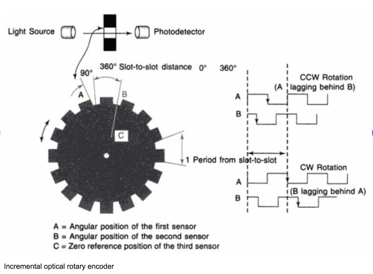
...for some info about encoders see https://www.researchgate.net/publication/305649159_Re-gripping_analysis_based_on_implementation_of_slip-detection_device_for_robotic_hand_model - from where the attached pic is from - and https://www.analogictips.com/rotary-encoders-part-1-optical-encoders/ (interestingly - only optical and magnetic encoders are mentioned...)
1 Attachment
-
• #31
@PeterD, I was going for a full dot-matix display... but your 7 segment does the job as well... with much less effort...
You can browse several of my conversations that deal w/ 7 segment displays and how to logically control / drive them, for example Retro Bubble Displays driven with 74HC595. Since you plan to use Neopixels, instead of the multiplexer reading out the character / digit buffer and mapping it to the 7 segments, you write a Neopixel data stream composer that is reading out the buffer. Furthermore, you do not need to interval the update of the display since you have knowledge of the update events from your controller. You still can use an interval based approach, but the the first thing it does is check for change since last time.... and because you use only a few bytes for representing the scores, memory is not an issue...
For the 7 segments think of some 3D printed segments from partially transparent filaments, ten you need not that many LEDs and have less heat dissipation challenges... (but still be conscious to protect critical elements from direct sun exposure).
-
• #32
Just found this cool 7 segment design
https://blog.hackster.io/ginormous-7-segment-display-with-neopixels-f96fcd168704
-
• #33
@MaBe, thanks for posting this link. I would construct it with a bit more diffusion effect. I recently made some practical - micro controller free - 3D print and LED application, pub'd 'somewhere else':
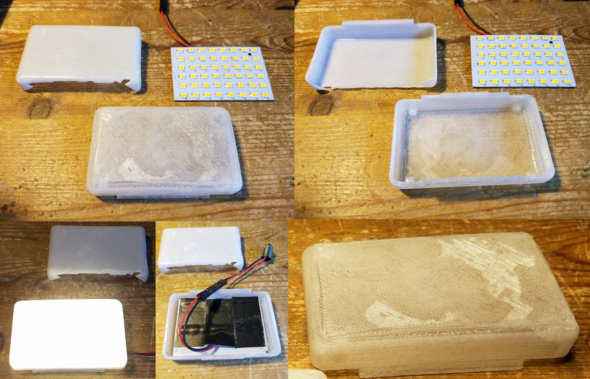
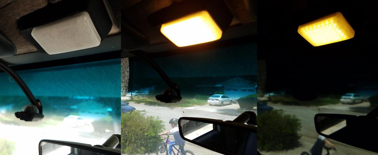
Have my 3D Anet A8 printer for a while now... printed many fun and useful parts; most for my HAM radio class and some other (model railway) things. BUT now the first real thing for practical use: The RV Cab light cover gave way to (UV) sun light and needed a replacement. Same time I switched from incandescent to LED. And that's how it looks.--- Filament is 'clear' ABS, 0.15mm layer, thickness of light surface is 1mm. Douse - filled and painted - finished part w/ Acetone for reinforcement by 'melting/netting' the layers and increase transparency... Some of the Acetone could creep into some of the (not so tight) layers and created this globe map pattern of oceans and continents.
I see the value of using Neopixel because then no multiplexing is needed,... offloads the micro controller and allows even colors.
2 Attachments
-
• #34
For the big scoreboard, I think I'm going to use a thick (40mm or more) black MDF wooden board.
With a CNC milling machine, I'll mill all the "segments" and drill the 12 mm holes that hold the LEDS. I will mill also the pockets that can hold diffuse plexiglass. On top of this MDF board can I glue a printed design of the scoreboard. And on to another blanc plexiglass to make the front waterproof. The plexiglass is mounted against the MDF. that will asure that the plexy can handle the impact of a baseball. .. I hope that my explanation is a bit clear ... ;) -
• #35
...will be quite a heavy board... what do plan for overall size? ...power supply?
-
• #36
Diffusion kills brightness. From some distance it's impossible to identify individual LEDs on a 144 LEDs/meter LED strip, saving the diffusor. You've already posted a video - did you try this outside at daylight already?
Handling a baseball impact, I'd say the plexiglass itself should be strong enough, without an extra MDF backplate. I'd prefer a more lightweight build. Milling the MDF is a lot of work, even using a CNC. -
• #37
The board will be 1.8 by 1 meter (approximately).
And I know it will be heavy, but is will be mounted on a wall, so that's not a problem.
Maybe I will glue pieces of MDF on each other were I need to mill the pockets. That will save weight.
And I can make use of an industrial CNC, Milling time will be 1 hour more or less, so that's a problem as well :).
I tried to put my "prototype" outside, and 7 leds/segment (WS2811) is enough. But maybe not enough with white light in combination of a diffuser. Because the not burning segments are white as well.
Later this week I'll build 2 digit version, with a black background and a diffuser just to test.
As power supply's, I have 5V 40A power supply. That's sufficient for 300 WS2811 leds. And I'll inject power each 50 leds.Version 2 will be based on 64x64 led panels.
But I don't have experience whit this. It should be nice if I can control this by HDMI. But maybe I need a kind of converter to control 50 of these panels by HDMI.
For the moment I plan to complete the "low cost" model first ;)
-
• #38
Lexan is stronger - practically unbreakable - and allows you to go lighter.
40A is plenty... full bright - white - pixel takes 0.06A, which means that you could run more than double the planned 300 ones. To simplify your setup, you could have the segments 3 dimensions, like letters that are put up on a storefront.
To go completely contrast safe, think of something like flip-dot - with or without additional LED or split flap design...
...or this I came across a while ago: (electro) mechanical 7 segment display - https://hackaday.io/project/161215-largemechanical-hand-activated-7-segment-display and https://hackaday.com/2019/01/26/7-segment-display-is-3d-printed-and-hand-cranked/ ... commercially available... just not in the size you are looking for... https://www.youtube.com/watch?v=hJ4INheOEjE
- with some modifications... you may already researched this anyway. -
• #39
what do you mean by "flip-dot - with or without additional LED or flip-card design..." ?
-
• #40
Flip dot display:
And there are flip dot displays available that have in addition to each flip dot also an LED that is on if the flip dot is 'on': https://hackaday.io/project/159415/logs?sort=oldest
The split flap display is like this: https://www.youtube.com/watch?v=lW0fk_sIdic
- and a nice split flap display you find at: https://www.tindie.com/products/scottbez1/split-flap-display-kit-4-characters/
Instead of split flaps, you can also use rotating disks... probably the simplest to implement with a few steppers...
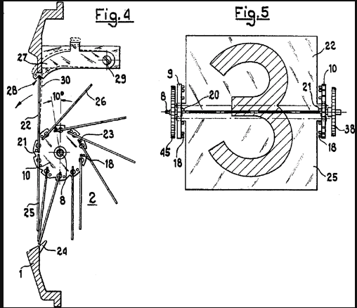
Attached is split flap tech drawing / cross cut as found on wikipedia
1 Attachment
- and a nice split flap display you find at: https://www.tindie.com/products/scottbez1/split-flap-display-kit-4-characters/
 Robin
Robin maze1980
 allObjects
 MaBe
MaBe

 PeterD
@AkosLukacs thanks - I will make some tests in coming days and share results. I was just wondering if there is a better way of doing this.