Espruino Wifi battery? #4472
Replies: 1 comment
-
|
Posted at 2017-05-14 by Robin Sun 2017.05.14 Hello @Thinkscape, Although I have no experience with the WiFi version; I'll agree with you the documentation could be improved with this bit of detail. Do you currently have the WiFI board, or are you considering a purchase? Have you checked out these resources:
So, it appears that 3.3v could be supplied to pin J2-3 , Gnd to J2-1 , rather than and instead of powering via the micro USB
This would mean of course, tack soldering your JST connector choice to the top of the header pins. Schematic:
This detail should suffice in the meantime until another with actual hands-on experience can assist here. Robin EDIT:
Although this pin is on the downside of the regulator, there isn't any reason schematically this couldn't be used as a supply pin. However, just now locating this comment, leaves me with a bit of doubt, as it is specified as an output pin. So, not sure if my suggestion to tack solder a connector here is prudent. Maybe, J2-2 labeled VBUS (on schematic VUSB on diagram) could be used as long as the battery supply is above the voltage regulator input requirement.
Posted at 2017-05-14 by @allObjects http://www.espruino.com/WiFi Docimentation states that you have three (3) mutually exclusive powering options:
The pins are 2nd and 3rd in row next to micro USB. 1st pin - GND - is ground (-). http://www.espruino.com/WiFi was made with breadboard friendliness and integrated Wifi communication in mind. While you are developing and are connected, you can use the micro USB. Disconnected you can feed it over the VUSB (+5V) or +3.3V pins - or - some of these USB power packs to micro USB. Most/Some of these power packs include a 3.7V Lithium cell that you also can connect with some extra caution to 3.3V. The extra caution is that a fully charged 3.7V cell can deliver up to 4.4V which will destroy the processor. To be safe, you can connect it directly to the VUSB pin, but towards the capacity end of the 3.7V cell and some load, the cell may not have enough voltage anymore to drive the voltage regulator so that the regulator still puts 3.3V out (as to @robin's comment). USB power banks use internally a booster to always put out 5V, and since the booster's efficiency is always less than 100%, you spend some capacity on it, but on the other hand you are safe. You can also connect the USB power bank +5V to the VUSB pin. The behavior of Espruino regarding serial / console out is different when powered connected / USB vs powered through pins. There are several forum entries about this (google espruino+console+usb+connected). One last remark: to operate onboard ESP8266 Wifi, you need a good power source. It can run from a standard 500mA USB supply (with sufficient capacitor in parallel), but more than 500mA is better. Today's phone power adaptors deliver 1000..2100mA (1.2A) and are a great option. (To go elaborate, you modify a USB cable the way that it allows you to power not only from your connected computer but also from other source: cut the 5V line and crimp male and female connectors to the ends, crimp a connector also the the GND line. This gives you all the options... including the one when disconnecting form the computer on the computer side you still have power through the micro USB connector...) Posted at 2017-05-15 by Robin Thank you @allObjects for clearing that up. I liked your concise explanation within the pp detail on battery differences.
I was surprised to learn that my PC had a USB3 port along with the USB2 ports. The 500ma value has a bit of latitude when on a USB3 port. 900 big ones! https://en.wikipedia.org/wiki/USB_3.0
For what it's worth, I've not had an issue, yet, . . . running WiFi over USB2/USB3, but I heed your warning. That said, I chose to power my little critters with an external supply, lest I suffer the wrath of extra electrons wanting to take an undesired path while I'm on a productive breadboard design streak. Posted at 2017-05-15 by @allObjects oops... fixed the 1.2 to 2.1 which I wanted to put out in the first place, but since I was talking mA kept it going and messed up... (500mA from USB 2.0... thanks for educating me about the 900mA of USB3.0. I'm using some older machines that have only USB 2 and I managed to have them switching of when fumbling with Espruino, ESP`8266 and some other stuff. It always helped to put some extra capacitors on the 5V input as well as close to the ESP8266, as you can see in :the picture attached to this post](http://forum.espruino.com/conversations/276831/) - on bread board as well as on the ESP8266 ESP-01 directly. Posted at 2017-05-15 by Thinkscape Thanks for the explanation. It'll be my first IoT board purchase, i'm new to all that. As a side question, you've mentioned 500mA being too little to power it. I was under the impression that the SoC and Wifi would be much less power-hungry and could operate on something for months on a 2000mAh cell - my use case will be a temperature sensor: thermistor + resistor + Erduino WiFi, probing the temperature every 60s, posting a handful of small packets via HTTP via WiFi. What is your experience with ESP8266 and power draw? Posted at 2017-05-15 by Robin Mon 2017.05.15
It is good that you are asking the right questions and I'm sure you will be excited making the correct IoT choice. Supporting @gfwilliams with an Espruino brand IoT board purchase would be appreciated.
You are correct @Thinkscape under certain conditions. I believe it was @gfwilliams that covered this in a post I am still trying to locate. I'll do my best to summarize until that link is found. The idea is to run the device on a 1% duty cycle running at the 20ua drain 99% of the time. These devices consume around 50ma to wake up, 100ma at impulse for mild number crunching, 200ma during warp drive, and up to 500+ma using WiFi etc. The GPIO pins can source around 25ma but the total chip source is only around 100ma for all IO out meaning around five LEDs at 20ma each. As one can see, during excessive WiFi use, an external (wall-wort) power source is recommended to save on battery draw. Still seeking that link, ESP8266 - NodeMCU - led and ds1820 temperature example http://www.espruino.com/Wireless+Temperature+Sensor http://www.espruino.com/Tutorials EDIT Mon 2017.05.15 Still searching for that post but did find the following: @allObjects posted the chip GPIO data: 'maximum current from the espruino pins' See p.59:
Posted at 2017-05-16 by @allObjects Power consumption is usually measured 'integrated' with di/dt over some t... for example for blue tooth - which is just another type of RF communication - see this Measuring Bluetooth Low Energy Power Consumption pdf document from TI. Figure 26 thru 28 on pages 21 thru 23 show the great fluctuation in power consumption: 'high' power over very 'brief' periods and 'very very low' power of 'long' periods. Such behavior is not knew... and you may have wondered why for each IC on a board there is/are very closely capacitor/s to 'catch' - smoothen out - these power demand spikes so they do not 'back-fire' and jeopardize the power on the rest of the circuitry... ESP8266 has similar behavior. Especially at the beginning spikes of up to 300mA have been measured (caused by RF calibration of the circuitry). Some details you can find here: esp8266_power_usage. To find the proper battery configuration - capacity of the battery - depends on two things: what is the peak draw, how often over how long, and what are the low draws and for how long... To not wear down a battery too quickly, the peak draw should not go above 10% of the capacity/hour - for example - a cell may have a nominal capacity of 225mAH (22.5mA over 10 hours) - and therefore, peak should not be higher than 22.5mA in order to nominally guarantee a capacity of 225mAH. Drawing much less than the 22.5mA will 'let you live longer', but there is also a limit to that because each battery has an inherent self discharge. These battery parameters you can find in the respective data sheets. Posted at 2017-05-22 by @gfwilliams I think this is all sorted now, but just to sum up on the power usage thing: 500mA is fine (I think supposed peak power draw is around 300mA, but it's always good to over-engineer!). When Espruino WiFi is 'asleep' it is very power efficient, but it does draw quite a lot of power when WiFi is on. If possible I'd try and connect and send data less often than every minute to get the best power usage - maybe every 15? For properly low power radio solutions I'd take a look at something based on Bluetooth Low Energy though, since it can happily send data much more quickly without the power usage overhead. Posted at 2017-05-22 by Thinkscape Awesome, thanks! Posted at 2017-05-26 by furuskog What about a Lifepo4 3.2 battery? Posted at 2017-05-26 by trusktr Total newb here, the above info isn't enough for me. When I'm in an electronics store,
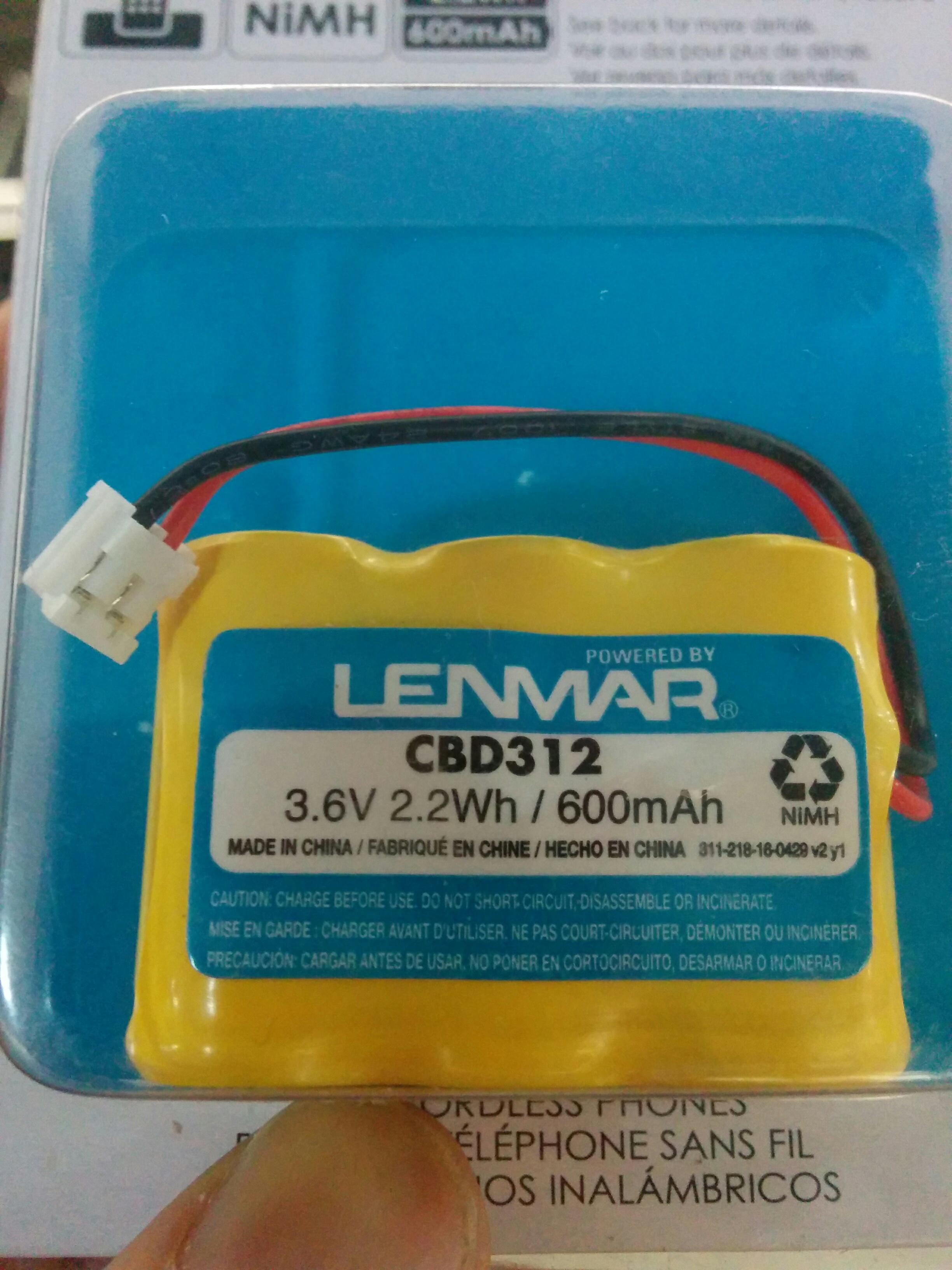
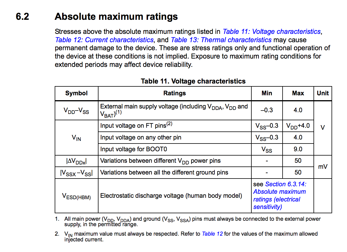
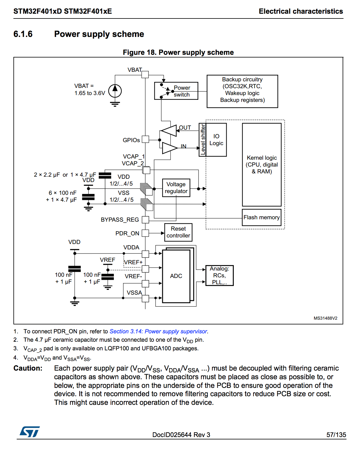
Thanks in advance! Posted at 2017-05-26 by trusktr Would this work? Attachments: Posted at 2017-05-27 by @allObjects Initially, I posted what's below the ////////////// line. ooops... What was I thinking... Lipo?... which goes 'way' beyond the max rating... sorry for confusion. Anyway, this is the update and good news: ** You are perfectly fine to connect this battery directly to the 3.3V because its highest voltage and worst case is below the maximum ratings. I attached the power schema and maximum rating of the mc from the manual linked on Espruino Pico Reference page. ** Notes:
////////////////// As stated earlier, you may have various issues by directly connecting this battery to 3.3V:
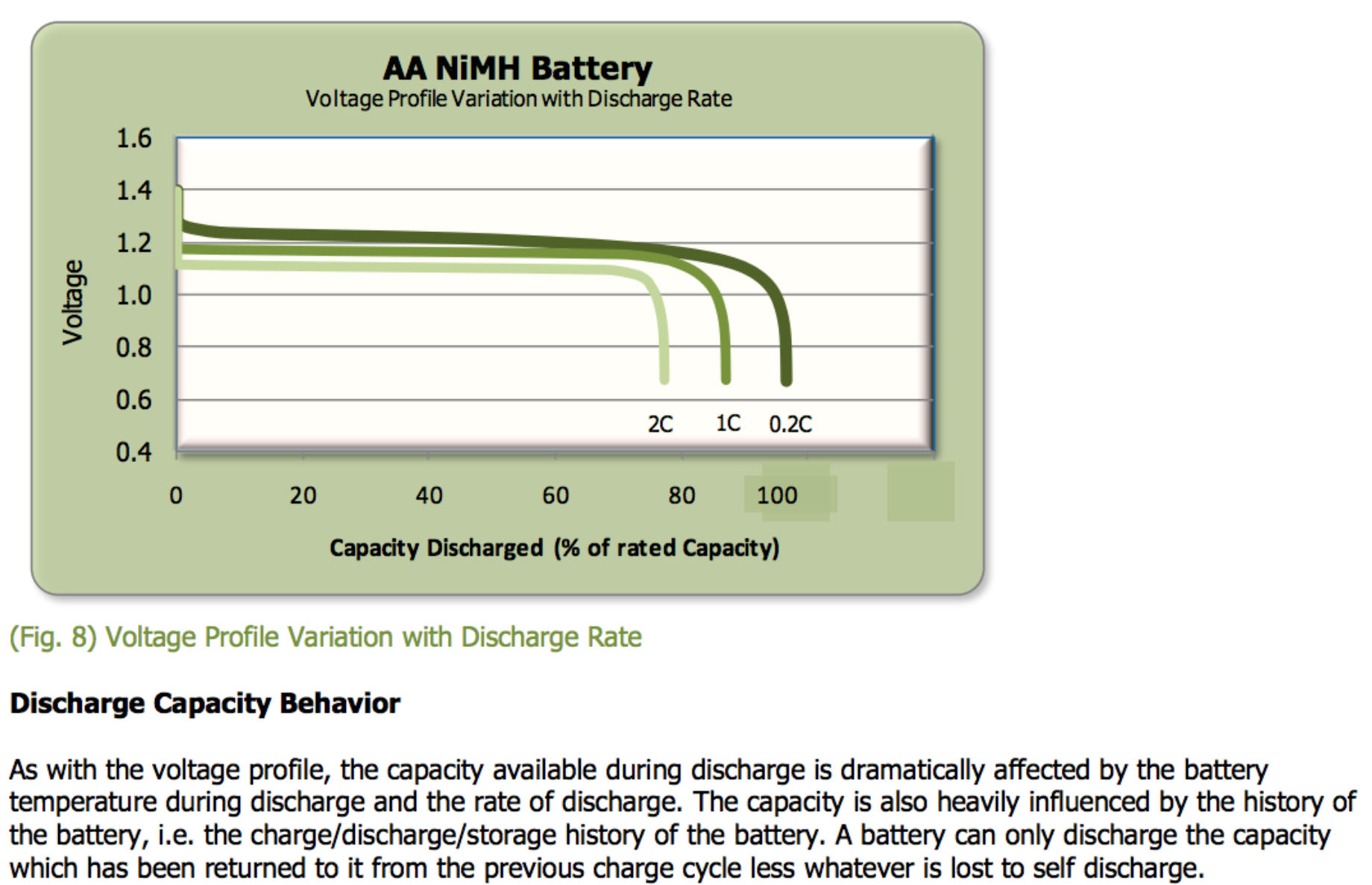
As you can see from the various graphs in attached battery spec file, you see the voltage from every cell from beginning to be too hight to continuously dropping. It gets really low when approaching 80% discharge... (C in attached graph means Nominal Charge - 1C means 600mA discharge over 1hr, 0.2C means 120mA discharge over 5hours). These batteries are really great and work nicely for where they are used: cordless phone that you use while talking, but then you put it back on the station where they get recharged... Using 4 such cells are perfect and give you ample reserve to run through the 3.3V voltage regulator to give you a stable power supply even beyond 80% discharge. You can get them in AA or AAA size and nice battery holders for 4 cells as well, and you can charge them with conventional chargers. PS: ...have not stakes in organization from where I pulled the tech file, but it is an excellent piece of pager explaining many things greatly... Attachments:
Posted at 2017-05-27 by @allObjects EDITED previous post. [:> Posted at 2017-05-29 by trusktr @allObjects Hey, thanks for your helpful intent, but its still advanced for me. You mentioned the Pico, but I'm using the WiFi. Does that make a difference?
Does the 3.3v pin go inside the red or the black side of the connector? And what about the extra wire (if I connect to red, the black is left over)? Posted at 2017-05-29 by @gfwilliams @allObjects I'm not sure you're considering the ESP8266 that's also on the Espruino WiFi? That accepts a maximum of 3.6v, and as you noted when fully charged the 3.6v NiMh battery could be a little over 3.6v. @trusktr you've got 3 main options. USB power bankIf you're at all worried about wiring up, I'd say just using a USB power bank is by far the best/easiest option. Wiring directONLY DO THIS IF YOU'RE SURE YOU ARE NOT GOING TO PLUG INTO USB WHEN THE BATTERY IS CONNECTED Get a LiPo battery - any single cell battery (3.6/3.7v) will do fine, and using http://www.espruino.com/WiFi#pinout as a guide, wire:
Some stuff you could use: Battery: https://www.adafruit.com/product/328 Pretty much any LiPo battery would work (I tend to use old mobile phone batteries), but you'll find it way easier to charge if you have one with the 'JST PHR2' connector that everyone uses on it. Nicest solution - separate power supplyUse a special 3.3v power supply like this one: https://www.adafruit.com/product/2745 The supply is designed to produce a steady 3.3v from a LiPo battery regardless of what the battery voltage is. It'll get the most life out of the battery and will allow you to plug USB in as well if you want to. Using http://www.espruino.com/WiFi#pinout as a guide, you'd need to connect:
Hope that helps - I think that covers the best options you have... Posted at 2017-05-30 by @allObjects @gfwilliams, didn't really think about the ESP8266... which in deed does not like anything much over 3.6V. According to the battery specs though, the voltage falls very quickly to 1.2V. Posted at 2017-05-31 by trusktr @gfwilliams Thanks! That helped a lot. The battery I pictured above has that same (JST PHR2) connector, and says 3.6v. Would that one work then?
If the battery is fully charged (and is above 3.6v), could that break (burn) the espruino? Should I get a voltmeter to check before wiring it up?
If I get that battery, would the white JST PHR2 connector fit onto the GND/VUSB pins directly? As for the separate power supply option, which does sound best based on what you describe,
Would I need to fork the black wire to two wires (like a snake tongue) and connect to both pins, one on each board?
Just to confirm, this is to the 3.3v pin (which the schematic calls "3.3v output"), NOT the VUSB pin? Posted at 2017-06-01 by Robin @trusktr are you dead set on battery power at this time, e.g. are you really at the development stage and will be writing code for the near future? If so, I would consider @gfwilliams suggestion of a dedicated supply to avoid the hassles with battery use. You will be thankful, we know this based on experience. Have you considered using a cell phone charger? I run my Espruino projects using a leftover 5v 800ma cell phone charger with a micro USB plug on the end, which I plug into a micro USB receptacle whose pins fit nicely into the solderless breadboard. Mine has been running non-stop for three months now for just pennies to the all mighty power company. My 0.02 worth. Posted at 2017-06-01 by trusktr
Yep, am aiming to have something finished by June 30th for 3DWebFest. That's a good idea, I think I will get that power regulator! And yeah, plugging in a cell phone battery sounds nice, so it can last long. Thanks for the tips! I only need the device to run for 3 to 5 minutes during the show. :D Posted at 2017-06-01 by @gfwilliams
Yes, it'd be fine.
Only if you are going to wire it up as @allObjects had suggested - if you do as in my post then you don't need to worry about the voltages (as long as the battery isn't much over 5v!).
Unfortunately not - the pin spacing is different. You might be able to bend pins and force it but I'd suggest a separate connector if possible (you can always buy the socket quite cheaply and then solder that direct to the pins).
Yes - it doesn't matter how you do it though - you could use one long bit of wire and strip the insulation in the middle if you wanted.
Yes, that's the one! Just to add though - the USB power pack idea is easy, cheap, and tidy, and it'll easily run the Espruino WiFi for far more than a day, which would probably be enough for you? Posted at 2017-06-02 by Robin Thr 2017.06.01 From #14 From #21 From #19
As @trusktr had the same question, would @gfwilliams please expound on the following to add clarification for us all: It is given that: (links found in #2 above)
Q1: Was this distinction VBUS vs VUSB made for schematic software reasons and not a typo? Q2: What/Where is the connector showing VUSB/DM/DP or is this the input to the WiFi module? Q3: Under the assumption the micro USB connector is feeding the power, is it true that VBUS [ J2-2 ] is available as an output and that it is electrically connected to the input (after Fuse F1 perhaps) of the regulator as 5v (the source a USB port supplies), and therefore also supplying 3.3v as VDD [ J2-3 ] as an output? Q4: Under the assumption that supplemental power from a 3.3v battery is supplied, and that no micro USB connector is attached, that is could be applied as an input VDD at [ J2-3 ] bypassing the onboard regulator? Q5: Similarly as above, upto 5v could be supplied by a regulated supply to VBUS [ J2-2 ], thus using the onboard voltage regulator, producing the 3.3v to the rest of the circuitry, and at VDD [ J2-3 ] as an output? Thank you Gordon Posted at 2017-06-02 by @allObjects
That's true when you power thru 5V, because the 5V go to the 3.3V onboard voltage regulator and show up at the 3.3V pin for feeding other devices that need 3.3V (but at the same time do not overload the regulator when all the onboard things go on). It is an input when powering with 3.3V directly. This is the reason that you should power it from both sides, because then the powered regulator fights the 3.3V powering device... (Btw, this constraint is only for Espruino-Wifi. Original board and PICO have an additional component on board that prevents - in default setting - havoc when power is applied to both, USB/5V and 3.3V. Posted at 2017-06-02 by @gfwilliams
There's no specific reason for that - it's because the design started off as the Pico design and had power supply components removed.
They're test points on the rear of the board
VUSB is connected directly to the USB power supply, with no fuse. This was probably a bit of a mistake, but was done because people had complained in the past that there was no way to get the full power output from a USB wall supply/phone charger when using something like the Pico. The regulator supplies 3.3v, but there won't be any problem supplying 3.3v from elsewhere - unless for example you're using a battery that is less than 3.3v (in which case it will be charged up to 3.3v when USB is connected).
yes. as I'd said in the last post - supplying regulated 3.3v to the 3.3v pin would be the most sensible way to power the device.
Yes. If no input volatge is detected, the USB hardware won't be powered up, so the current draw will be less.
Yes, you could do this - again as I said in my last post. However there are some issues:
Posted at 2017-06-02 by Robin Fri 2017.06.02 Thank you @allObjects for the simple response on dual power. As there appears that re-editing seems to plague this thread, [me included ;-) ] isn't there a missing 'not' or 'never' in the sentence 'This is the reason that . . . ' and a missing closing ')' found in (#24) ? @gfwilliams thank you for the clearing that up. I missed (what the device did\was) the 'LM3671' reference in post #22 and your similar responses to those posed by my suggested clarification. I felt it made more sense to ask explicitly so as to tie in with the documentation that appeared to have missing detail. I'm sure that the topic re-visit will help @trusktr and assist @Thinkscape and others as it has me. Maybe there is a simple way to show how to connect, which pins to connect to, using the three power input choices in table format, perhaps? Bi-Directional [ J2-3 ] gave me fits until I studied the schematic, as the docs currently state it is an output pin. |
Beta Was this translation helpful? Give feedback.
-
Posted at 2017-05-14 by Thinkscape
After http://www.espruino.com/Battery
I'm confused... "the original" has a JST connector built in, the Pico has instructions on how to solder on a JST connector, but there's no mention of "Wifi" model.
How can I power it?
Does it support soldering on a JST connector like Pico?
Am I supposed to only power it via USB connector?
Thanks.
Beta Was this translation helpful? Give feedback.
All reactions