-
• #2
Display     NodeMCU     ESP-12   Colour
LED         3V3         3V3       N/A
SCLCK       D5          GPIO14    Green
DN<MOSI>    D7          GPIO13    Yellow
D/C         D2          GPIO04    Orange
RST         D1          GPIO05    Brown
SCE         D8          GPIO15    Red
GND         GND         GND       Grey
VCC         3V3         3V3       Blue
BackLight   GND         GND       Purple
this board is different than @Ducky 's as the backlight is taken to ground to enable
-
• #3
Hello - do you have any suggestion about how to do this on a bare ESP8266 12E? Many Thanks
-
• #4
Not sure what you are asking here - what is the issue you have?
-
• #5
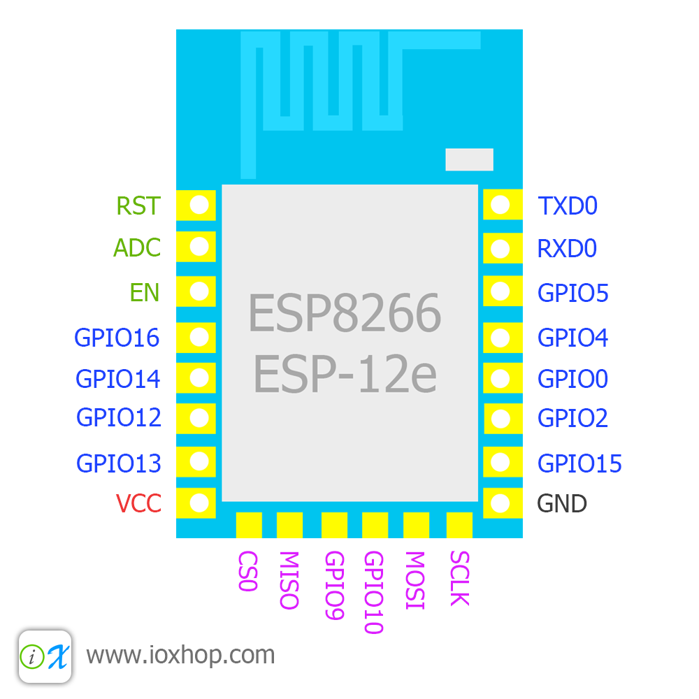
The issue is that I've tried to make the same thing by connecting the ESP8266-12-E to the nokia directly (no NodeMCU board), and I see the Nokia screen blank.
My setup looks like the one in this picture:

I think there must be something with the NodeMCU.D* pins mapping... have you tried to use a Nokia 5110 display without the NodeMCU board?
-
• #6
Are you using the code above?
Keep the code the same, and you need the wiring to the pins:GPIO4, GPIO5, and GPIO13, GPIO14, GPIO15.
It looks like GND, VCC and backlight are ok - as the display is on!
If you are powering everything off the FTDI board it might not have enough current to power everything.
1 Attachment
-
• #7
Hi - yes, same code.
Had already wired to GPIO4, GPIO5, and GPIO13, GPIO14, GPIO15 before but I gave multiple careful checks. Note the GPIO15 is also already pulled down with a 1Kohm resistor, it should be wired like this if I want the ESP to boot I think - I connected it to CE on the display anyways.
I tried to switch this to various pins (GPIO 2, GPIO0, GPIO12) but nothing is shown on the display. I have tested the display with an arduino so that shouldn't be the problem.
Also I've tried with the following code as well:
var g;
var contrast = 0;
function begin () {
  console.log("begin");
  SPI1.setup({ sck:NodeMCU.D5, mosi:NodeMCU.D7 });
  g = require("PCD8544").connect(SPI1,
    NodeMCU.D2 /* RS / DC */,
    NodeMCU.D8 /* CS / CE */,
    NodeMCU.D1 /*RST*/, function() {

    console.log("executing with contrast " + contrast);

    g.clear();
    g.setContrast(contrast);
    g.setRotation(2); //Flip display 180
    g.drawString("Hi Esp8266",0,0);
    g.drawString("Hi Esp8266",0,10);
    g.drawString("Hi Esp8266",0,20);
    g.drawString("Hi Esp8266",0,30);
    g.drawString("Hi Esp8266",0,40);
    g.drawLine(0,0,84,48);
    g.flip();

    setTimeout(function () {
      contrast += 0.1;
      if (contrast > 1) { contrast = 0; }
      begin();

    }, 800);

    console.log("Executed");
  });
}
E.on("init", begin);
save();
And I see an output like the following on the console:
 _____                 _
|   __|___ ___ ___ _ _|_|___ ___
|   __|_ -| . |  _| | | |   | . |
|_____|___|  _|_| |___|_|_|_|___|
          |_| http://espruino.com
 1v85.tve_master_66fde09 Copyright 2016 G.Williams
Espruino is Open Source. Our work is supported
only by sales of official boards and donations:
http://espruino.com/Donate
Flash map 4MB:512/512, manuf 0xe0 chip 0x4016
>echo(0);
=undefined
Erasing Flash.....
Writing......
Compressed 25600 bytes to 3437
Checking...
begin
executing with contrast 0
Executed
begin
executing with contrast 0.1
Executed
begin
executing with contrast 0.2
Executed
begin
executing with contrast 0.3
Executed
begin
executing with contrast 0.4
Executed
begin
executing with contrast 0.5
Executed
begin
executing with contrast 0.6
Executed
begin
executing with contrast 0.7
Executed
begin
executing with contrast 0.8
Executed
begin
executing with contrast 0.9
Executed
begin
executing with contrast 1
But nothing to do...
-
• #8
Get rid of the on init and save code- get it working on direct upload, as you might have issues with the pinmode setup.
You could swap out gpio15 for gpio9 - not sure what the nodemcu:dx pin that corresponds to..
-
• #9
Thanks for you help @Wilberforce it now works! It worked on direct upload in the beginning, then I figured out the pin setup via dump() and now I got it working with the following code:
var DISPLAY_CONTRAST = 0.49;
var LINE_HEIGHT = 6;

digitalWrite(D2, 0);
digitalWrite(D4, 0);
digitalWrite(D5, 0);
pinMode(D0, "input_pullup");
pinMode(D12, "input_pullup");
pinMode(D13, "input_pullup");
pinMode(D14, "input_pullup");
digitalWrite(D15, 0);

function drawText(oDisplay, aText, iX, iLineHeight) {
  aText.forEach(function (sLine, iIdx) {
    oDisplay.drawString(sLine, iX, iLineHeight * iIdx);
  });
}

function begin () {
  SPI1.setup({ sck:D14, mosi:D13 });
  var g = require("PCD8544").connect(SPI1,
    D4 /* RS / DC */,
    D15 /* CS / CE */,
    D5 /*RST*/, function() {

    g.clear();
    g.setContrast(DISPLAY_CONTRAST);
    g.setRotation(2); //Flip display 180
    drawText(g, [
      "Line 1",
      "Line 2",
      "Line 3",
      "Line 4",
      "Line 5",
      "Line 6",
      "Line 7",
      "Line 8"
    ], 0, LINE_HEIGHT);
    g.drawLine(30, 0, 84,48);
    g.drawLine(30, 48, 84, 0);
    g.flip();

  });
}

E.on("init", begin);
save();
It looks amazing! so thanks again for your help!
 Wilberforce
 user63099
Thanks to @ducky http://forum.espruino.com/comments/12949433/
Here are pictures showing the wiring colours on a breadboard.
3 Attachments