confused about power #5342
Replies: 1 comment
-
|
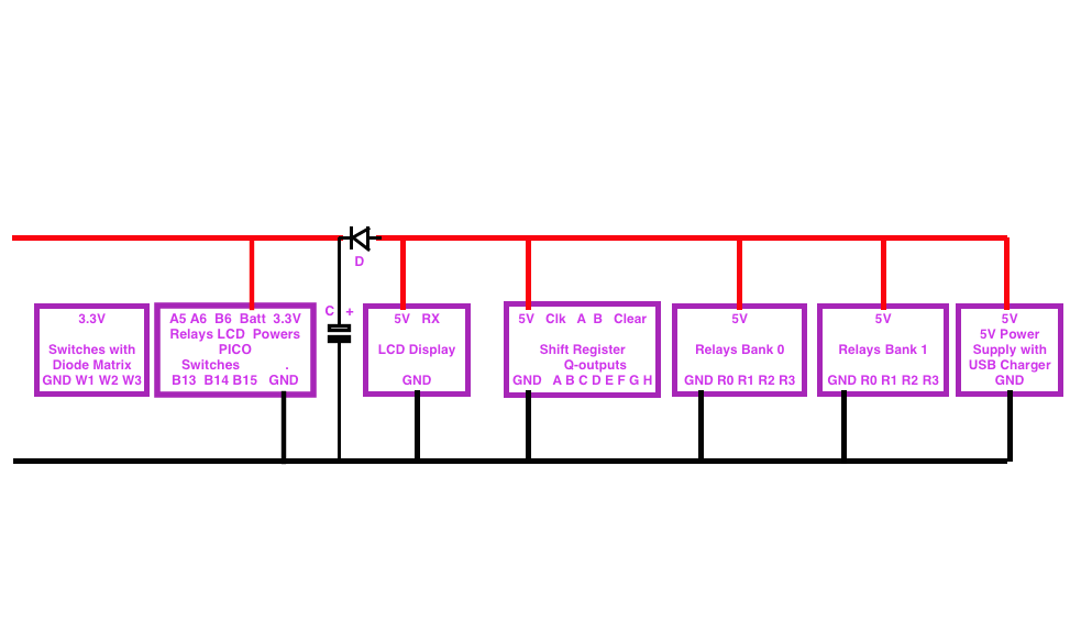
Posted at 2016-05-28 by user58511 pretty pictures Attachments: Posted at 2016-05-29 by @allObjects You need to be a bit more specific about your hardware building blocks to answer your questions. For example: Pico drives a driver that drives the relays... but what is in between the Pico and the relays boards with 4 relays each? Decoupling capacitors are a good idea... but often it is not good enough... decoupling or actually have 'separate' power supplies for the different (types of building blocks) is a good idea. For example, want to have a very stable and clean power supply for your control electronics, such as the pico - and the chip sitting on the breadboard in the power strip. I assume it is a shift register or port expander to drive the 8 relays (it cannot be a ULD2003 driver, because this driver has only 7 outputs... leads me to the question: how many relays do you control? Last but least your cat cable from Pico to this 'mysterious' chip has only 8 leads, which allows you to control directly - or parallel - only 7 things, because one of these 8 MUST be the shared ground. This is a good segue way to talk about shared Ground: shared ground is the only way if you do not use opto coupling to have galvanic/electrically separate circuits. Shared Ground is a good starting point, no so good is shared power or insufficiently decoupled power supply. Next would be to look how you get the power from the black box to the strip for the 'mysterious' chip and the relays boards. If it is the cat as well, then you can drive 6 relays only... on the other hand, you may have extra leads for getting the power to the 'mysterious' chip and the relays boards. On a different note: Each relays consumes about 30mA... and that can bother your 'power world' too... Using batteries is a good test stepping stone to figuring out the problems... but the batteries do not last long... except you make them rechargeable and somehow recharge them. In that case, the act like large decoupling capacitors and smoothen out the power as well as buffer it for the peaks when you need more than the power supply can stably provide. First you start of with one relays and strip unpowered to test functionality. Assuming this works, you add the rest of relays and do some testing. With a Multimeter you can measure the relays contacts (if the relays boards do not have LED(s) on the board to show on or off status. For the power supply, you have to be sure that your power supply pushes enough power for all your devices... I see some additional 'things' in your 'black box'. If your power supply delivers 5 volts and is strong enough to run all things, you can create a decoupling: use a diode (Anode, not-ring side) from plus to (Cathode, ring-side) to PICO Bat and and a large capacitor of 1000uF from diode Cathode/Pico Bat to Ground, that stabilizes PICO board input power pretty well. You do even more and add a capacitor between Pico 3.3V and Ground. You can also have the latter capacitor... but it is a bit a stress on power up for the regulator if the capacitor is big. Both is for sure better. The relays board can usually have their own supply because they haven an open-collector kind of driver on them, which means, as soon as you put TTL-High minimum - 2 Volts - on the input, the switch this alternate power to the relays coil and do the on switch, the a bit more than 2V is better, but not more than power supply voltage of the driver). Btw, TTL-LOW is max 0.8 Volts. The minimum of 1.2 Volts difference is to prevent noise from switching... Some drivers need less to switch on but are then also more susceptive to noise. To all that sharded ground applies. Take my comments with pinches of salt... I spent the majority of my time in software as well... btw, would be interested to see some of your control software published here... Posted at 2016-05-30 by ClearMemory041063 To drive relay coils, most circuits use a diode across (in parallel with) the coil pointed so that current doesn't flow when power is applied to the relay coil. When the power is removed from the relay coil the diode suppresses the inductive kick from the coil. Some example diagrams: Posted at 2016-05-31 by @gfwilliams Hi, that looks like a really nicely built project! From what I can see, you're using relay modules which have all the drive electronics inside. The only gotcha I've found with those is that often they have pullup resistors that pull the inputs up to whatever voltage you're powering them from (in this case 5v). But because you're using a shift register (which I guess is also running off 5v) you should be fine. How is the Pico being controlled? Is it from the switches in the final box? It might be that the long wire to the end box is actually picking up noise caused by the spark from the relays (I've had this happen). There are some things that might help:
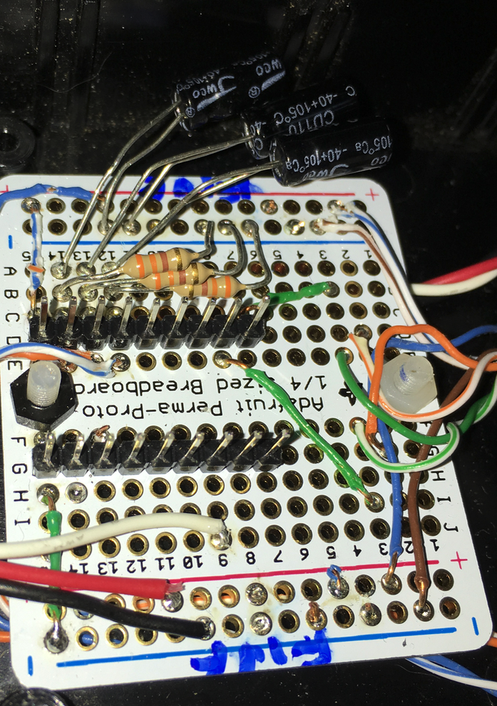
But yes: Sharing GND between different voltages should be fine - I'm not sure you'll notice much of a difference when powering from a battery though. Posted at 2016-05-31 by user58511 Gordon: I have lots of old USB cables with ferrites on them, if I clip one of those onto the black cable which end should it go near ? AllObjects: I powered the shift register with 3v -- should I switch that to 5v ? AllObjects: I am interested in the 'decoupling' could you please re-state it more concretely ? Here are more pictures, a better description, a parts inventory, and the code I used Thanks, Attachments:
Posted at 2016-06-01 by @gfwilliams I'd stick the ferrite on the end nearest the Pico. I can't promise anything but it's worth a try... I have a really similar setup for my bathroom lights (4 relays of that type, and then a 1M long wire that goes to the light pull) and I was amazed at the amount of noise it received when using the internal 40kOhm pullup resistors - I had to move to much lower values to get it to work reliably and not turn on and off all the time :) I'd definitely power the shift register from 5v - that should help a lot too. The way the relays usually are (pull down to turn on) it means that if you power them from 5v but feed them with a 3.3v signal, the drivers are 'half on' all the time, because 3.3v is still less than the 5v they're expecting to be turned off. Posted at 2016-06-01 by user58511 Ok, everything is 5v now and I rewrote the switches.js to behave a little better when I hook up multiple switches in the future -- thanks! I'm still interested this talk of decoupling and capacitors -- but I don't really know where to put them exactly, or what strength to use... And I found a ferrite tube and some ferrite rings, so I can thread the cable thru the tube and re-crimp the end -- but I can also thread individual wires inside the control box. Suggestions? I'll report back as to any reduction (or otherwise) in ouija activity (update) I found some clamp on ferrites in my pile of servo stuff !! So I've clamped both the cables after they come into the pico Box -- I have two more of these as well as the rings, what else should I apply them to? The wires that go to the relays are too thick for these, but I could pass them thru a few rings (not long enough to twine around rings unless I replace.) Oh, and I took the pico off the board and tipped it up so you can see the female header on the pico and the male header on the board -- make sit easy to swap in a pico with updated code. And, I love having female header on the pico so that I can just use it as it's own mini breadboard for testing code. (A big THANKS goes out to allObjects for that idea !! http://forum.espruino.com/conversations/276831/ ) Attachments: Posted at 2016-06-01 by @allObjects Thanks for the details. As @gfwilliams says, shift register (74164) be powered with 5V, as well as the relays board. Just feed it from there. Pico output to the shift register inputs is well in specs with MC 3.3V output. Just cap the 3.3V power from pico to shift register and connect it to power from the relays board. Looks like the USB charger that you use as power supply / source is strong enough to run all your equipment. 'Amazon/vendor says': 1500mA... which most likely is what they say. To decouple and stabilize the power for Pico, do not directly connect the 5V from power supply to Batt: put a diode in between and then put a capacitor between Batt and GND. I took a look at the SW. What I like is the modularization. Looking at the individual components, I see some challenges in the dynamics and stability / predictability in the cooperation with the hardware. Surprise to me is that no debounce works the best and that the spi write is in a timeout, which means that control continues immediately. Could you elaborate a bit more on the implementation of your 'keyboard'/switches schema? Attachments: Posted at 2016-06-02 by @gfwilliams That looks great! I'd say that's all you need with the ferrites - I wouldn't worry about the mains wires, it's more to try and combat interference caused by sparks in the relays themselves. Hope it works better now! Posted at 2016-06-02 by user58511 No real improvement in ouija action... More reaction to relays I think... I want to do the decoupling thing now, I can figure out where to put the cap & diode thanks to aO's diagram -- and I have these caps but don't know which ones to use http://www.amazon.com/Projects-EPC-201-Value-Capacitor-Pack/dp/B00CQOM1IC aO: the switches code has been rewritten to be much clearer about it's intent. It's working a lot better now. I've attached the latest copy, I meant to upload it last night with the update to the control.js file (see reply #8) Attachments: Posted at 2016-06-02 by user58511 Ok, so now everything is 5v (except for the clock/data lines to the shift register) -- I have a 100uF cap - will that do? I'm ordering a set with 1000's in it. How do you know how big to use? What's a good ref for a total newbie (who's bad at math) for this kind of stuff? if I wanted to order optoisolators what kind would I order? Posted at 2016-06-03 by @allObjects Hold your breath buying more hardware. If switching the power for the shift register from 3.3V to 5V (and the decoupling with diode and a 100uF (or a few in parallel)) do not calm down the relays from jittering, the problem (dog) lays (buried) somewhere else. When I asked about the switches, I was thinking of the schema, how the diodes and switches are matrix wired. With three lines you are able to catch 8 states, where as the state 0 is the 'unusable all-off' state, leaving seven (7) different watch-detectable states. There may be some 'trickery; to work with less then the twelve (12) diodes I would need to reliably do it (with momentary-on SPST - Single Pole Single Throw - switches in mind vs momentary-on SPDT - Single Pole Double Throw - switches; with the latter ones you may get away with less diodes by using both on states... but Espruino is so fast that it detects the none-on when the switch switches, and with the diode setup it may trigger erroneously on top of the multi triggers by the multiple watches....). Furthermore, on all three input lines you have a watch... depending your circuitry and the expected switch value more than one fire and may create your jitter... Multiple get serialized and then are processed one after the other in JS 'tasks' (callbacks). Therefore, after one triggered, you clear all watches, 'wait' some time and ignore any others that do trigger, then read the lines, do the work, set the watches for the going off, do the same finicky things for the off as you did for the on, and then set the watches for 'on's again for the next cycle... Attached 'my' schema I was thinking of to check for seven (7) switches. And here the (partially tested) code:
The
Since you may need the value as an index for all kinds of things - especially with the display - use the default value and build the bit list just when you need to send the value to the shift register. The conversion is really easy: There are other solutions, but with three (3) lines you get only six (6) switches, and with four (4) lines you get twelve (12) switches (needs only six (6) diodes). If you can spare six (6) lines, you can detect nine (9) switches without any diode. Attachments: Posted at 2016-06-03 by user58511 All of this is to set up some switches for my mom who is bedridden and has little use of only her left hand -- the coiled wire runs from the wall to the rolling beside table (keeping itself off the floor) so I am limited to 4 wires. Your diagram perfectly explains my diode arrangement. I've not done the decoupling and diode yet - I was waiting to see if I had to have a 1000uf as you had first suggested. I'll try with the 100uf. The problem is not so much jittering (not staying put once set) but rather that outside power use affects the system. She has an electric hospital bed and when we run it down, that can cause the circuit to switch off the light -- it seems to me that it's not just affecting the shift register or the relays at that point, because the lcd says the switch is off. Will it be all right to decouple the circuit more than once? I'd like to decouple it for the shift register as well as at the pico. thanks for that extra code, I'll let you know how it works if I try it. Posted at 2016-06-03 by @gfwilliams I'd suggest that you put 3x 0.1uF capacitors (anywhere near that) between PV1/2/4 and GND in the box with the Pico, and that you use very low value pull-down resistors (300 Ohm-ish). What are you using as pull-down resistors currently? I don't see anything in your circuit? If you're not using any, that would almost certainly be your problem :) Posted at 2016-06-03 by @allObjects As @gfwilliams points out, the pull-down has to be strong enough to keep noise in check. The Espruino built in pull-downs are pretty weak - only 30..40k. The limitation to 4 wires is not an issue, because the additional pull-down resistors are anyway best placed close to the watched input pins. Since you run everything outlet powered anyway, you can have an interval triggered update of your peripherals. Having the controlling Espruino power decoupled / stabilized is good enough. Using the same (simple) decoupling technique for the shift register does not really work, because the shift register requires 4.75V minimum according to datasheet, and a regular Si diode has typically a 0.7V drop leaving only about 4.3V to the shift register. Some Ge diodes have a lesser drop - about 0.2V - but it is not a typical application. You can use a MOSFET which gives you better results (same concept as Espruino uses on the board when powered by battery: see PICO Reference, POWER, AND THE FET/B0 JUMPER). Before going there, work on making the switching robust. The extra pull-down will for sure increase the noise resistance. You may start with just one diode and one pin and one switch and a pot in series with the current limiting fixed resistor and find optimal working point. Posted at 2016-06-03 by @allObjects On a different notice: measure the resistance across bothth jack connectors and spiral phone cable... may be there is something fishy... or went somehow wrong when working / crimping on it. Sometimes it is a simple electro-mechanical issue... like forgetting to put the plug into the wall outlet... ;-) Posted at 2016-06-03 by user58511 ok, most of that has left me in the dust... I have and can do: 100uf & diode decoupling for pico, 330Ohm resistors on the switch pins. I have .1uf caps, but I don't know if gordon means 3x per line? I should have time this weekend to solder on this thanks guys! Posted at 2016-06-03 by user58511 Also - what is FET ? Is that MOSFET ? I need something that will let me turn on conductivity between two wires -- these look ideal http://www.espruino.com/mosfets but I can't find the one they say is good (3v version) for sale anywhere thanks! Posted at 2016-06-04 by @allObjects 100nF caps go parallel with 330R resistors (see updated schema; updated also previous posts). Btw, since Espruino PICO's inputs are 5V tolerant, you can also feed the switches box with 5V - which increases noise immunity. Feeding 5V gives you an option for a nice UX touch: put an LED into the switch line for each switch: it will light up when the related switch is pressed! Posted at 2016-06-04 by user58511 Well I'm glad your diagram showed the resistors going to ground, I was going to put them inline I had to substitute 0.1uF polarized for your unpolarized 100nF (I love google) --- Do you have a suggestion for something that I can use to create continuity between two wires, without introducing any current into them --- Attachments: Posted at 2016-06-05 by user58511 The other caps arrived without the 1000uF's (with 2200, 3300 & 4700uF's) Is it a problem that my wires from the switch boxes are "closer" to the pico than the Caps & R's ? It's getting time to completely redo this board... Posted at 2016-06-06 by @gfwilliams What you've done with the caps + resistors looks perfect. I have to say with 330 ohm pull-downs it should be really solid... I'd be amazed if it accidentally triggered. Posted at 2016-06-06 by user58511 At this point - 48hrs in - the only ouija activity has been internal to the powerstrip. Twice so far I've heard relays click with nothing but EMI to cause it. I'll be decoupling the 5v power next - then re-doing the boards && then publishing it in the projects section. I am looking for some way to induce conductivity between two wires - FET/MOSFET look good but I can't find the 3.3v ones mentioned in the tut. Posted at 2016-06-06 by DrAzzy The MOSFETs mentioned in the tutorial ( IRF3708PBF ) are available from digikey and mouser, and probably any similar electronics supplier. Not available from "hobby vendors" and ebay. If you're able to do SMD work, there are hundreds of amazing transistors with specs that boggle the mind. Through-hole options are extremely limited if you need gate voltage of less than 4.5v, unfortunately. To address this shortage of through-hole MOSFETs that work with low gate voltages, I sell low-voltage logic level MOSFETs mounted on breakout boards to make SMD MOSFETs usable to people who prefer not to work with SMD parts - (4-channel ones big and bigger, and SOT-23 ones for ligher duty by the six-pack - prices start at $3/6pk for the SOT-23, and $12/14 for the 4-channel ones) . Some models are available with several different types of FETs mounted on them, at different prices (see product page) Posted at 2016-06-06 by user58511 I fear my ignorance is showing.... I am looking for some way to induce conductivity between two wires -- I thought these might do it, but they rely on sharing a ground with the wires being connected... I have a device that exposes two leads, when they are connected with a mechanical switch then the device is actuated. I want to connect those two leads using the pico, but I can't introduce any current into them. I don't really want to use a mechanical relay for this (like the ones in the powerstrip) but I will if I have to. A relay would do the job since it's powered totally independently from the wires being switched I guess I'll go search for solid-state 3.3v controlled relays I should have started a new thread for this question... Something like this? http://www.futurlec.com/Relays/JRC-23F-03.shtml Posted at 2016-06-07 by tage It is really dangerous for someone with such lack of knowledge in electrical safety to be messing around with mains voltage, especially if there are "signal" wires coming out of the contraption, and these wires are accessible so someone can touch them. Posted at 2016-06-07 by @gfwilliams I'm not going to say 'It's fine' unless I get sued, but @user58511 seems to have been pretty careful. Most electricians will have very little idea about actual electronics. It doesn't mean they're at risk of electrocuting themselves or those they work for though. Just because @user58511 is willing to ask for help about problems with electrical interference doesn't mean he doesn't know about electrical safety. Also, those relay modules look pretty good to me. I've seen plenty of commercial stuff that has far less of a gap between high and low voltage than they do. @user58511 I think the thing you posted is just another relay? If you look for 'solid state relay' in eBay you should see a bunch of things that will switch mains voltages... Internally, SSR modules use a Triac (which does have a physical connection to the wires it's switching), but the module contains other components including an opto-isolator, to ensure that the 2 wires going in are completely disconnected from those going out. http://www.ebay.co.uk/itm/272159069775 uses an OMRON G3MB-202P looks like a good bet. Having said that, SSRs only work for switching AC power (otherwise you can turn them on, but never off). If you wanted to switch DC in an isolated way, without using contacts, then I'm not sure you can buy a module - you might have to make something with an opto-isolator and FET. Posted at 2016-06-07 by user58511 Tage, thanks for your concern. But I think there may be some confusion. I am not trying blindly to substitute relays to get rid of the problems with the EMI. I'll be decoupling the 5v DC power to try to finish accomplishing that. That being said, if you think the sain-smart relays were a bad choice to drive little 1&2 amp loads, I'd sure like to know what I might replace them with. You do raise an interesting point tho' as my contraption does have wires coming out of it that are not intended to carry mains voltage. Are you are saying that if there was some arcing situation within the powerstrip that mains current could exit it via the signal wires and be available for contact? In that case I think I'd be lucky in that the pico would die and the circuit would then be unable to be closed by contact, yes? In any case, would it be sufficient to place GFCI protection between the mains and my contraption? something like this: http://www.petsolutions.com/C/Aquarium-Power-Strips-Timers/I/GFCI-Outlet-Adapters.aspx (just to pick one that I found in a few moments searching.) Now these other relays are for a different project, and I should have started a different thread. This other project has absolutely nothing to do with the mains. The smaller relays that I'm looking at are to achieve conductivity between two wires to replace mechanical switches that are used in a battery operated device that considers the closing of the contacts a reason to send a complicated signal via bluetooth to a computer. Posted at 2016-06-07 by @gfwilliams Ahh, ok - so the relay you found would be pretty good for that (but you still need a nice way to drive it from Espruino), and SSRs wouldn't be useful. For small battery powered devices, you might find a simple optocoupler works fine for you - like: http://uk.farnell.com/isocom/sfh615a-4x/optocoupler-dip-4-tr-o-p/dp/1683350 It's rated at 50mA.... The only 'gotcha' there is as it's not a switch, you're going to have to make sure that you connect + and - on the device the right way around. Posted at 2016-06-07 by Wilberforce Here is a solid state relay that can switch DC: http://www.dx.com/p/ssr-10dd-solid-state-relay-white-silver-232097#.V1a2zm6eqrU There are different models, with different amp loads and for ac or DC. http://www.dx.com/s/solid+state+relay Posted at 2016-06-07 by @allObjects What is the reason not to use a relays for making connection between two wires of which you do not know what the dynamics are? In the original setup, they require a galvanic connection and I would stick with it. The question is also: is the original switch a momentary or and on-off switch? No matter what, you have power dependency... If it is a normal on-off switch: Case one: with a normal relays a power fail disconnects and you need a manual override (parallel on-off switch) Case two: with a bistable relays, a power fail leaves you stuck with the last state and you need a manual override (in series with one of the on of a on-off-on switch, where the other on make the direct connection). Posted at 2016-06-07 by user58511 Ah, let's all come to the same page: http://www.pretorianuk.com/j-pad I have one of these, and the person I'm doing this for can't operate the joystick, I chose the device also because it has the option to attach external switches. I want to make touch-pads so that I can close those [external switch] circuits programmatically. Gordon, those optocouplers are gorgeous -- I saw something like them in my searching last night but couldn't figure out if I could drive them from the pico as they didn't seem to mention Volts... Those mention 6v but in ways that I don't understand, and I don't know what your reference to 50mA means, the pico has 250mA to spread around so I'll have enough to drive these? Or I'll fry them unless I add a resistor? Anyway I'll grab some and see if I can make them work for me. I can swap the tip and ring on the external switch connections easily enough. Posted at 2016-06-07 by Wilberforce https://www.itead.cc/sonoff-wifi-wireless-switch.html Posted at 2016-06-07 by user58511 Wilberforce!! Those are sweet!! I have the wifi board on my pico!! They are a little overkill for this switching application -- but I'll be grabbing some of those to play with!! Posted at 2016-06-07 by @gfwilliams @wilberforce wow! Hadn't seen those before... (This is probably another thread, but does anyone have any, and have they tried flashing Espruino onto them?) @user58511 I'm pretty sure you treat it like you'd treat an LED - so a 100 Ohm resistor in series would work great. I think 6V is the maximum voltage you can wire it up backwards at before it breaks (and also the maximum you can put into the diode). With 100 Ohm resistors you're only really putting 15mA into the diode, so you could drive a whole load of them from the Pico without trouble. They will only switch 50mA on the other side though - so that's not going to drive anything very powerful. Posted at 2016-06-07 by user58511 Gordon, I'll have some of Wilberforces' find in a couple of weeks -- I'll start a new thread ! Posted at 2016-06-08 by ClearMemory041063 Adapters for surface mount chips. I've had excellent results with them. Posted at 2016-06-09 by Wilberforce I can't claim the sonoff find - it's being discussed on gitter https://gitter.im/espruino/Espruino There is now thread here with people testing... http://forum.espruino.com/conversations/288230/#comment13033307 |


Beta Was this translation helpful? Give feedback.
-
Posted at 2016-05-28 by user58511
I'm a purely software guy, I fart around w/hardware but this is the most complex thing I've ever done
I have built a pico controlled power strip - I opened up a USB wall-wart and stuck it in the powerstrip and ran 5v up to the Pico - then I ran 3v back down to the power strip to toggle the relays (using a shift register chip.) The intermediate box uses an old 5v LCD I had from my Arduino days. The relays are powered via 5v and triggered w/3v. The final box is just a connector for switches. I figured out how to stack diodes so that I can handle 7 switches from 4 wires.
problem #1 -- we call this thing the ouija-switch because turning other lights and/or tv's on/off in the room can make this thing turn outlets on/off, it's particularly bizzare to me because the LCD readout says that the relay has toggled. And of course it's getting driven by the Pico, so how can EMI (which it has to be) get up through the Pico out into the 3v world and make the software think I hit a switch?
answer #1 -- a guy at work with an EE background says that I'm getting power fluctuations causing harmonics which are screwing up the works, and that they can run rampant all over the place. He gave me 5-6 solutions using terms I had no idea (shunts, capacitors, inductors, etc.) until the 7th -- power the Pico from a battery, if all your problems go away then you can think about cleaning the power to the Pico. (and have I read notes from people on other projects involving relays say things like: use a decoupling capacitor and liberally sprinkle capacitors around your circuit. Liberally Sprinkle ?? I have no idea what-all he was talking about)
The Big Question -- if I throw a 9v battery into the middle box and connect that to the Pico then I will have 9v & 3v sharing the same ground, I used to have the 5v and 3v sharing the same ground. Is it alright to share the ground between 9v & 3v? Was the shared ground between 5v and 3v the source of my problems anyway? What should I do? I would rather not add a battery but rather fix whatever the original problem is that is causing the ouija-switch behaviors.
Beta Was this translation helpful? Give feedback.
All reactions