-
• #2
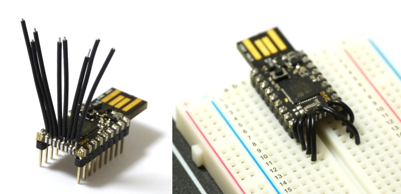
The top connectors come from an 28-pin IC socket with machined pins, and allow quick single connections without bread board.
The bootom are machned round pings. To fit both in the standard hole, I filed them half way of... ;-)
Adding the top connectors adds additional stability. I'm loking forward to an alternate board with 2x14 = 28 pins, breadboard friendly, with padds on the bottom for a ESP8266-09 and SMT pads on the top (for EEPROM / FRAM / MRAM / Atmel Crypto Chip,...
The Atmel Crypto / CryptoAuthentication devices have same pinout and protocol as serial EEPROM and include encryption engine and (secur) storage... for example Atmel-8664-CryptoMem-Low-Density / 1..8Kbit.
-
• #3
nice! maybe just make your own PCB?
-
• #4
Nice! Have you seen the 'prototype'/'breakout' designs on: http://www.espruino.com/Shims ?
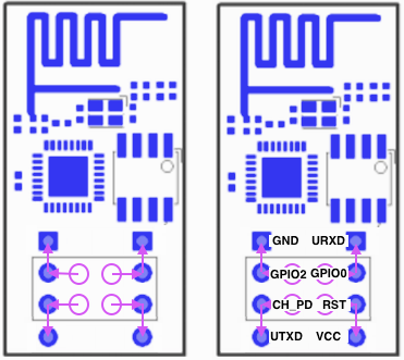
We could maybe change the wiring of '0.05" Breakout and Prototype Adaptor' to make it similar to your wiring? It'd be a bit wider, but would be easier for people to solder I guess.
-
• #5
...missed that espruino.com/Shims page...
a) Different layout and wiring for a shim with the shape like the version 1 and 2 for ESP8266 could be good option. If not extending in same plane, a thin one could be soldered on top rather on bottom. It culd even be soldered on a PICO that is already pinned... and to gain extra stability, the shim could include PICO's end holes.
b) I liked the narrow format because it still fits into adjacent USBs with 'decent' gap.
c) If to go wider, then only 0.1", that means: header pins will lay in the castellations and Espruino PICO becomes a classical JEDEC format: 2x14=28 or 2x20=40 pins... with machined pin headers it can then be 'socketed'... (but may not fit in adjacent USBs anymore).
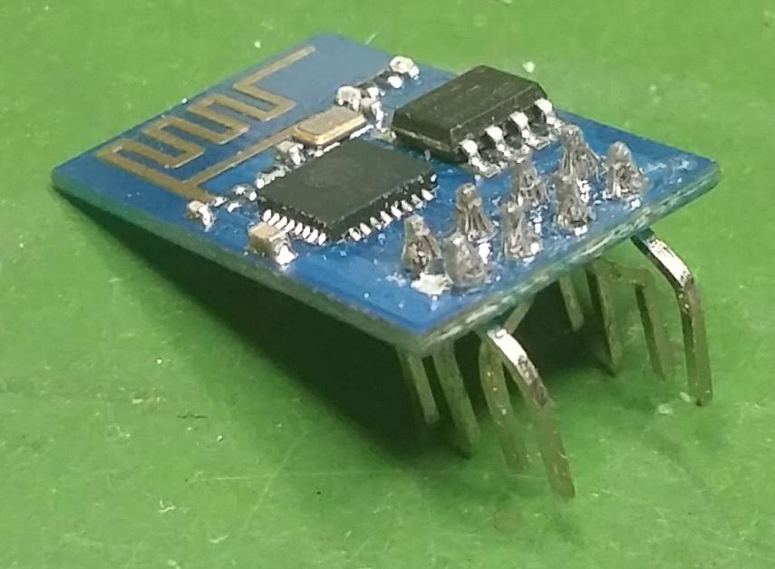
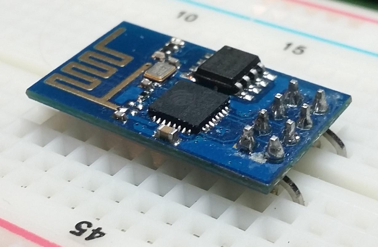
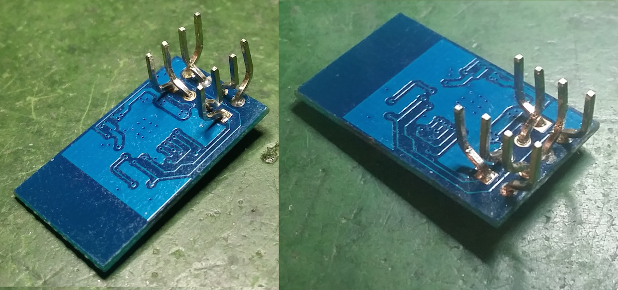
Btw, coerced also my ESP8266-01 to be breadboard friendly... as you can see the niche Crawler Critter in the attachments...
4 Attachments
-
• #6
Btw, coerced also my ESP8266-01 to be breadboard friendly.
Like that!!
-
• #7
PICO showing NOAA Marine forecast (line override not correct yet). Idea is to later on replace wifi with HF SSB / VHF and RTTY for receiving the text messages.
1 Attachment
-
• #8
Btw, coerced also my ESP8266-01 to be breadboard friendly.
Yes, that's really clever!
For some reason I never thought of bending ESP8266 pins that way... Always 90 degrees out, where it then gets in the way of the wires you're putting on!
That marine forecast is neat! Running off VHF would be really cool - can you get modems for that, or would you have to decode in Espruino itself?
-
• #9
I was thinking of decoding it in Espruino... may be it is a bit a performance challenge. - There are Android / iOS apps that pick up via microphone the crackle sound of the little speaker driven by plain HF SSB trans/re-ceiver signal... incredible... and show the RTTY messages on the screen...
-
• #10
Without knowing much about RTTY, it definitely seems possible... I guess if you're trying to analyse audio you might want to use compiled code to speed it up though.
-
• #11
Another cool version of bread board friendly PICO: this time 'a-la @Gordon':
Courtesy of @Gordon's PICO PC C64-style tutorial.
A nice centipede crawler!
1 Attachment
-
• #12
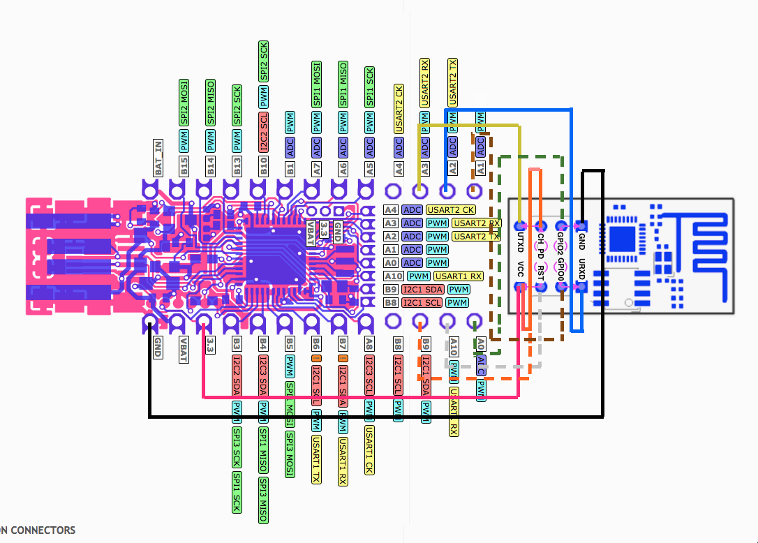
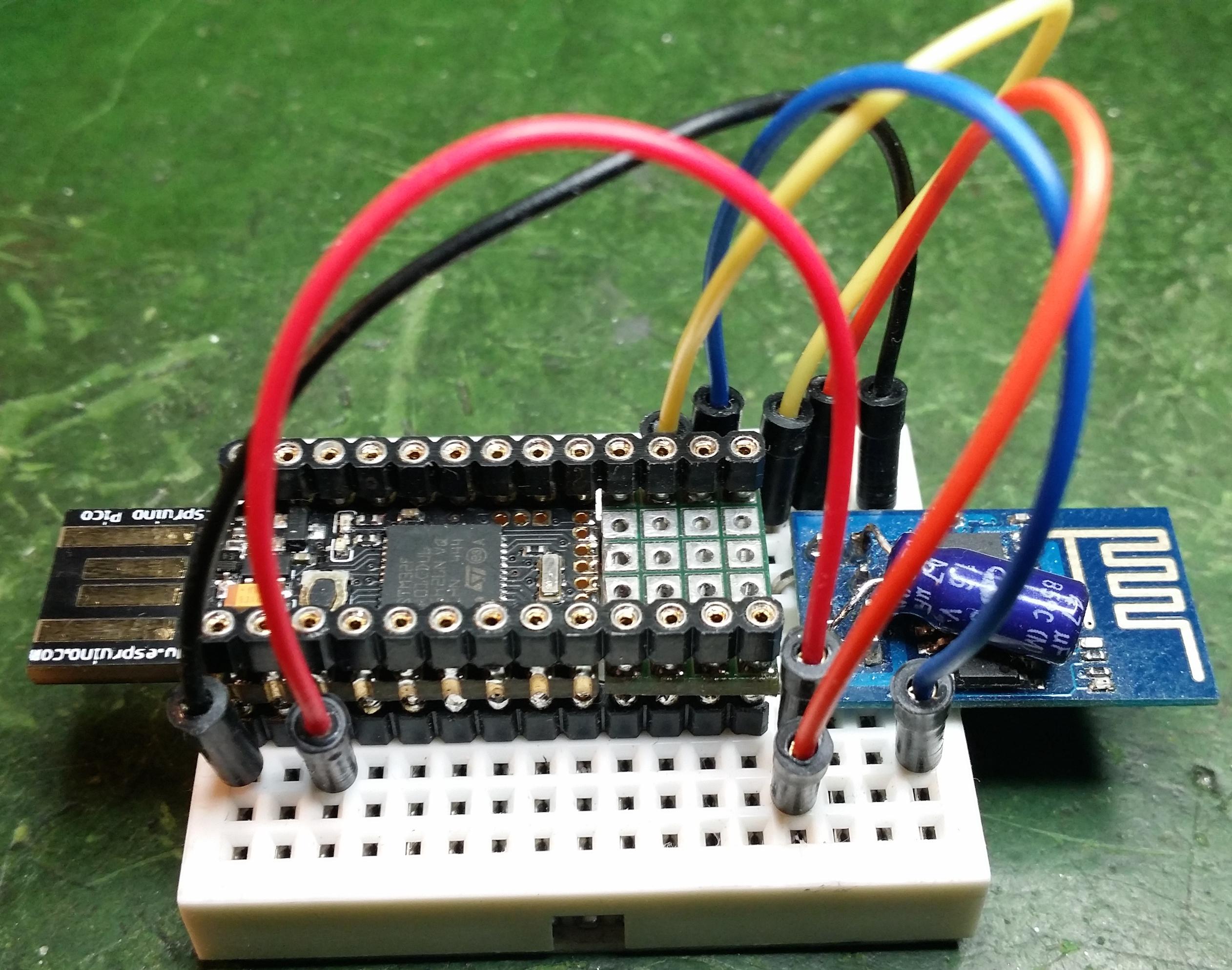
Wiring (dashed wires optional, orange has alternative: always connected to Vcc or Espruino B9 controlled):
1 Attachment
-
• #13
I am afraid MCP1703 will find it difficult to power both Espruino and ESP8266.
In the datasheet, 250mA is given as maximum current. -
• #14
It handles 500mA peak current, and I believe the ESP8266's peak current draw is more of an issue than its average current draw. I've used the ESP8266 with the pico without issues (with an extra capacitor, I didn't bother trying without it).
-
• #15
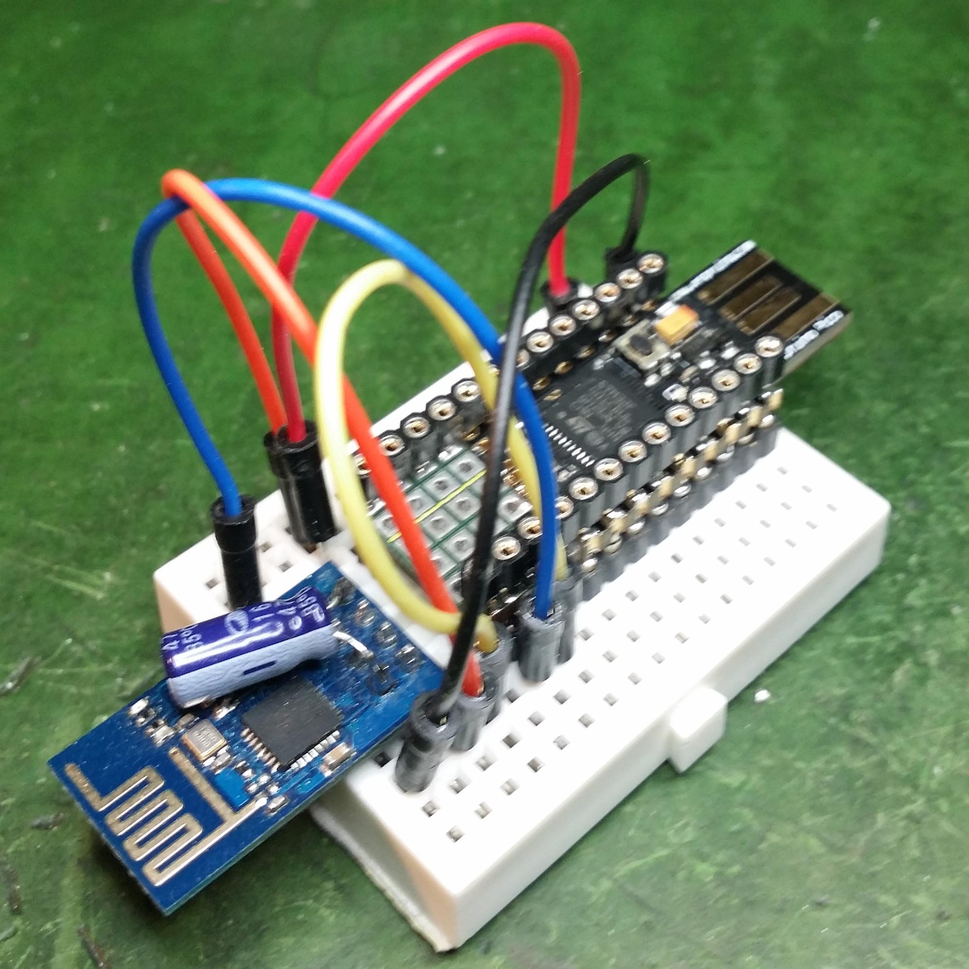
Works perfect, especially when having a good capacitor across the Vcc-GND with good connectivity, as you can see in attached pic: 'Capacitor for Life'. No matter where used: capacitor is always there... :-) - A wiggly capacitor of 'higher' capacity (on breadboard) can brown-out / reset ESP8266 and Pico...
1 Attachment
-
• #16
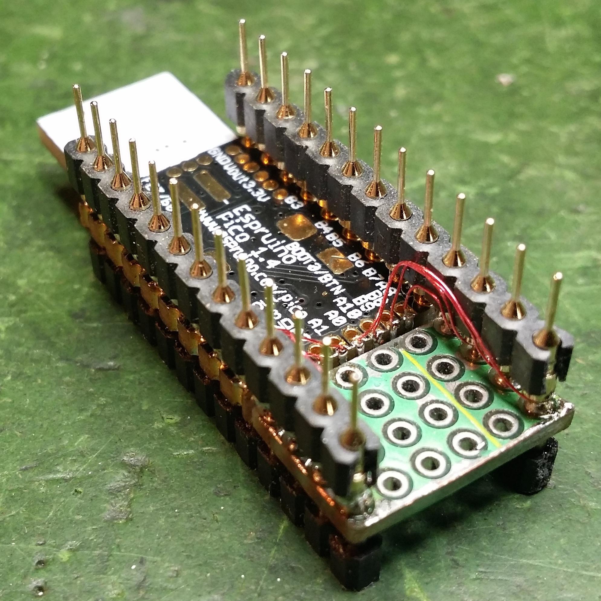
This version of Breadboard-friendly Pico has just the 2x4 0.05" pins brought out (extension by 4 pins on both sides), which makes it perfectly fit on a small bread board - as an interim solution until Espruino-Wifi becomes available...
The wires - lacquered copper - are soldered just to the castellation grooves and hide nicely. The extra 16 pads can hold what ever you think of and fits.
Having the extra row of connectors on top provides still enough connection points despite being on a small bread board - and easy access, for example as test points - to measure / observe signals on multi meter or digital analyzer 0r oscilloscope. To make the two (2) pins fit into the whole, I filed them a bit off on one side. Using round - machined - pins vs the regular header pins enables easy push on and pull off breadboard with much less force.
2 Attachments
-
• #17
@fdufnews many people use ESP8266 with the Pico's voltage regulator (that's what is done with the shim). It will run without an extra cap, but it's a good idea to add one.
As @the1laz said, it's capable of 250mA constant power consumption, which is more than enough for ESP8266. It can still deal with the odd peaks of power consumption.
If you ran from more than 5v, heat dissipation might trip it up, but from USB it's absolutely fine.
-
• #18
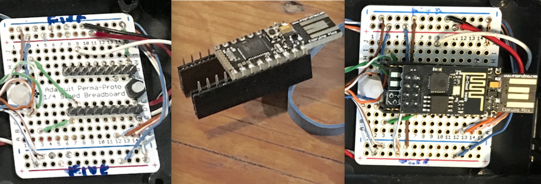
Another excellent version of breadboard (and production board) friendly PICO - courtesy @user58511 in application of PICO/Wifi/switches controlled power strip. It allows as well to bring out the 0.05" to dual inline 0.1" pins. Instead of soldering female headers or socket onto the carrier/application board, male headers do the job, ...and the same for breadboard usage.
1 Attachment
 allObjects
 tve
tve Gordon
 Ollie
Ollie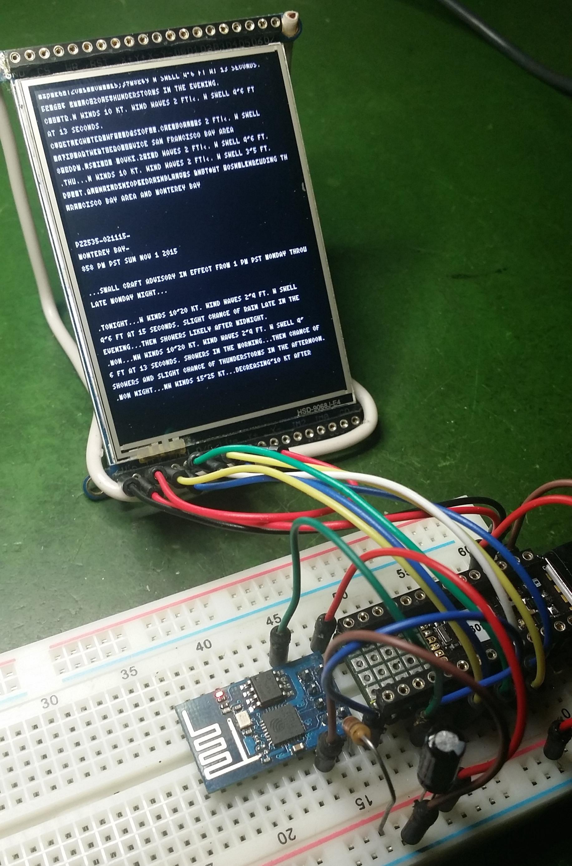
 fdufnews
 the1laz
1 pic is... - therefore: 3 pics = 3k words...
4 Attachments