-
• #2
I'm afraid Espruino doesn't support being a USB host, so it's not possible to capture anything from USB devices.
However you could still plug in old-style PS/2 devices and read data back that way if you wanted to.
-
• #3
Is it nearly impossible because of some constraints (memory, ..) or is it just not implemented until now?
If latter, is it possible to estimate the effort when using some existing library from STM e.g. http://www.st.com/web/catalog/tools/FM147/CL1794/SC961/SS1743/PF257882?
-
• #4
As I understand it, you need a bit of external hardware (a chip that will handle switching for OTG). If you don't care about powering the device you might be able to skip that though.
If you were happy building Espruino without the existing USB support, potentially it wouldn't be too painful to compile in that library and get something working... I have no real idea on the time required though.
-
• #5
Thank you, Gordon.
-
• #6
Hi there !
I was about to write a post on USB host stuff, but I got my info from above:
Espruino doesn't support being a USB host, so it's not possible to capture anything from USB devices.
While this is a pretty clear answer, and while I was hoping some hack existed to handle that, I'm still wondering how long it'd take / how hard it'd be to use a max3421e & handle it via SPI ?
Actually, if this was possible, I was planning to design a little shim that'd go on the back of the Pico to allow it to get keyboard key presses & log/save those to the flash or an SD ? ^^ , & also have the ability to "replay" them back later ( also, the ability to handle "key combos" to change modes 'd be neat ( .. ) )
-> so yes, a keygrabber :DI plan to digg that when I have enough time to ( & also finish that SIM800L lib ;p)
I'll be back when I receive the good stuff ( or as soon as I see nome neat feeback here ;p )
Cheers +
-
• #7
In addition to facilitate USB host, the GPIOs of the MAX3421E make it even a port extender. A cool thing for shimming to the PICO. I'm though inclined to use BLE to attach respective devices. It makes the connectivity less hardw(e)ary, but still has the challenge of handling USB input...
-
• #8
.. indeed a challenge :|
also, I just stumbled upon the following, which has a nice form factor ( although I'd prefer to have the Pico on top )
@allObjects yeah, the GPIOs are a neat thing to have, moreover if we can control those as easy as the Pico's own pins ( I guess for that, we may benefit from going "lower level ? " - though the USB inputs may already require us to do so .. )
for the part itself, I guess I'll have to check the european resellers for small qttys () since it seems I can't find it on ebay ? :/ .. )
-
• #9
Was checking the price... low quantities < 10 they cost about USD 8..9.
The GPIOs will not be that directly implemented and behave like in PICO, because all communication goes over SPI. The chip has to interrupts which could be connected to watched PICO pins... that at least could work... What about timing, that is a different thing.
-
• #10
That looks like a cool chip - I think it could definitely work. I guess it depends how painful the software is - if it has built-in support for keyboards/etc it could be quite easy.
-
• #11
Back ! :)
@allObjects I meant we could ease the use of the GPIOs the way we write the lib ;)
Also related to the MAX3421e:
https://www.circuitsathome.com/chome_downloads/UHS_mini_10.pdf
https://www.sparkfun.com/datasheets/DevTools/Arduino/USBHostShield-v13.pdfAs the guy(s) behind https://www.circuitsathome.com/products-page/arduino-shields/usb-host-shield-for-arduino-pro-mini have surely a good idea of caveats / hints on implementing it, I just sent them a mail, asking politely for stuff & forwarded the topic :)
@Gordon the following shield uses a different chip but is provided flashed to support different stuff http://www.hobbytronics.co.uk/usb-host-mini
I also wonder if the shim should still provide access to some of the Pico pins not used ( in other words, have wider, 2 row pinouts on edges of the Pico, providing access to the GPIOs of the MAX' ) ?
Anyway, I plan to add the schematics found in the datasheet / the Sparkfun's one / the CircuitsAtHome's one to a repo on 123D Circuits to easily share & update stuff on this ( .. )
Lastly ( not that related - only to Espruino ;p ): I had a little fun messing with a simple RGB LED ( common cathode ) with Espruino yesterday, and as I couldn't see any tutorial on these on the Espruino website ( yet there are at least 5 tuts on adressable LEDs ^^ ), the infos ( while really basic ) & the code may be helpful to others ( and may be also hugely improved I guess) :D
--> https://github.com/stephaneAG/Espruino_tests/blob/master/dummyRgbLEDsTests/fadeRgbLEDs_Espruino.js
Nb: the code is loosely adapted from the Adafruit's one ( thx guys ;p ) https://learn.adafruit.com/rgb-led-strips/example-code, and this one is also of interest https://learn.adafruit.com/adafruit-arduino-lesson-3-rgb-leds/arduino-sketch:)
-
• #12
Hi there :)
First of all, these links seems to be worth of reading ( even if I didn't have time to do so - don't get everything ;p ):
MAX3421E.pdf
game controller to USB mouse
USB Enumeration Code (and More) for the MAX3420E
Programming GuideAnd the above links are from this page: MAX3421E.html
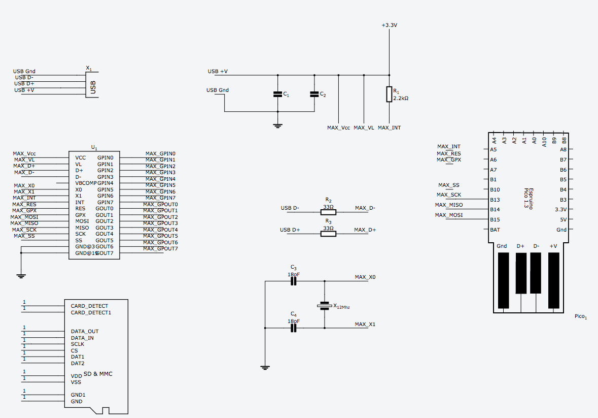
I did a quick circuit with was seems to be the bare minimum from the schematics I could find, it's hosted at the following url https://123d.circuits.io/circuits/2108375-espruino-pico-usb-host-shim/edit#schematic
Now, I already did a "schematic view component" for the Espruino Pico on 123DCircuits, but I didn't ( I know that's a shame, but I don't know Eagle .. yet ? :| ) add a correct PCB footprint for it ( got one, but no correctly sized, yet I need a clean one if I want that shim ;p ) .. any soul willing to help me ( and many others who use that neat tool, yayyyyy ^^) on this ?
Also, concerning the USB plug placement, I'm wondering what's best between a tinier yet fatter result, or a longer but thinner one .. ( and also what about having the plug "in the middle" of one end of the shim ? -> gotta draw some stuff from theses thoughts, to make that clearer ;) )
Code side, I wonder if it's best to digg the Arduino sources before/after/while reading the official docs, but at least for now, I don't know enough in SMT low level stuff to be of any help I'm afraid :/ ..
1 Attachment
-
• #13
back ;)
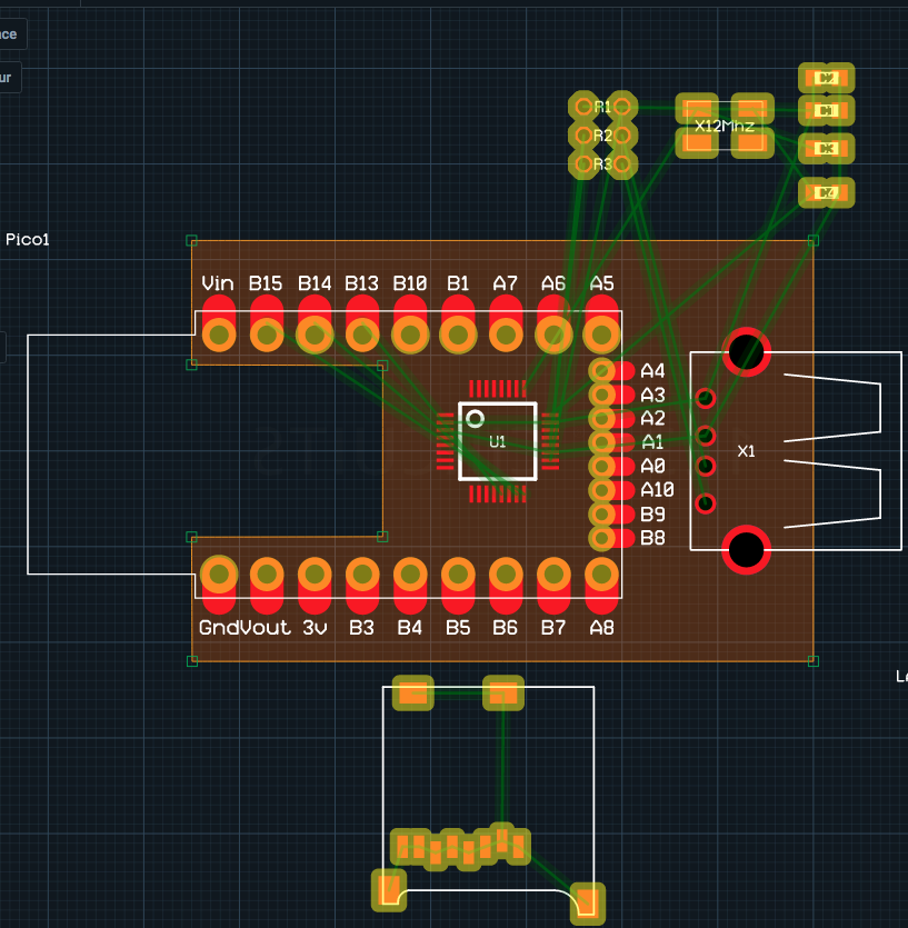
The updated version of the shematic & pcb using a correct Pico footprint is available at the following url https://123d.circuits.io/circuits/2182347-espruino-pico-usb-host-sd-shim
Also, I wonder what'd be the best way to position the micro SD slot while still allowing access to the LEDs, the button, as well as the back side of the Pico .. any hint / fork is welcome ;)
There's also the question of MAX_GPIN's & MAX_GPOUT's as well as the unused pins of the Pico
2 Attachments
-
• #14
I like what I see...
Did you think to pull/bring out the 0.05" spaced connections?... this could become a universal shim with the extra of having a USB host added to the PICO and have it breadboard friendly.
Just curious (without looking what difference is between the pins used to drive U1 and the 0.05" spaced pins): What is the reason to use other pins than the 0.05" spaced ones?
Since the device you mentioned has also GPIOs, why not make the shim longer and bring them in a row as well? ...or make a double header? Of course, double headers would not make it breadboard friendly...
-
• #15
Hi there !
@allObjects Thanks ;)
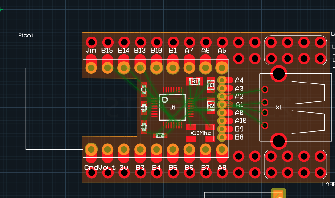
I plan to bring out the connections for [A4..B8] as a square of 4 pins on each side of the board, right next to the GPIN & GPOUT of the MAX, 8 pins each on both sides of the USB host plug
Somehow a reason: I don't know yet which pins require special capabilities & also didn't add the SD nor a bluetooth/wifi footprint yet :/ ( SD/Ble/wifi as three logging/extras capabilities 'd be neat :) )
Indeed, having the "square" pins & the GPI/O in double header configuration 'd mean no longer breadboard friendly ( although, the goal here is to minimize the size, but it's an idea to digg ;p )
I am currently wondering how to add the SD ( & what about using a flex ribbon cable to be able to "slip" it it some enclosure, right above the USB host plug )
here's an updated version of the pcb layout
Nb: I don't know the "best" footprint to use for the caps & the resistors ( I'm not used to SMD stuff yet ;p ), if you have any hints, they 're welcome :)
https://123d.circuits.io/circuits/2182347-espruino-pico-usb-host-sd-shim#pcb
1 Attachment
 Gordon
 luwar
luwar stephaneAG
 allObjects


An Espruino can emulate a mouse http://www.espruino.com/USB. What's with the "opposite" direction?
Is it possible to connect a mouse to an Espruino and capture mouse events?
I would like to use some kind of 3D mouse or wacom tablet as input device.