ESP8266_esp12 hookup #819
Replies: 18 comments
-
|
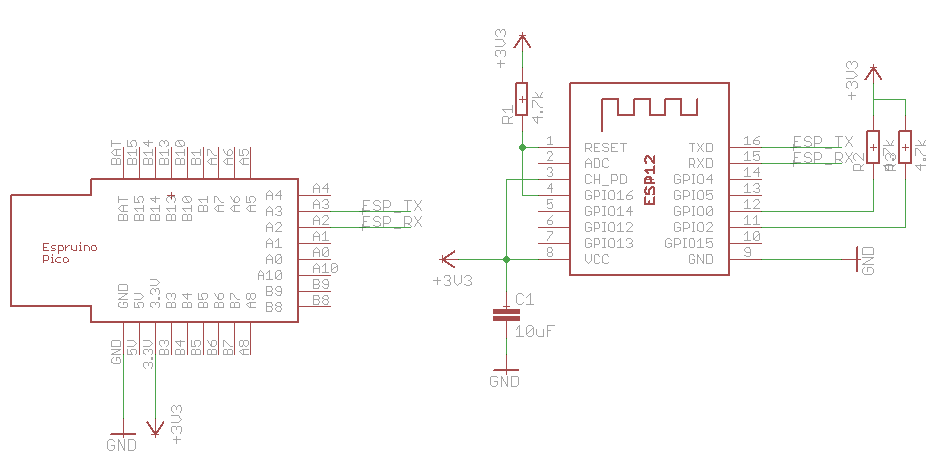
Posted at 2015-07-11 by DrAzzy Use a ceramic capacitor, they are not polarized. Ceramic is what you want for this anyway The resistors are needed (one of them is the pullup on reset), but the specific value isn't critical. They're just pullups. |
Beta Was this translation helpful? Give feedback.
-
|
Posted at 2015-07-11 by Jorgen DrAzzy is right - the components are needed.
|
Beta Was this translation helpful? Give feedback.
-
|
Posted at 2015-07-11 by DrAzzy 01 needs a cap, ime, otherwise it dies when it tries to do anything. They didn't put enough caps onto the module, which is a shame - this has been a pain point for Arduino users too, and it would have only cost them a few cents a unit to do right. |
Beta Was this translation helpful? Give feedback.
-
|
Posted at 2015-07-13 by @gfwilliams @user55329 so you tried the The extra components shouldn't be required, but as @drazzy says the capacitor could be handy to make WiFi connections more reliable. The resistors were just to allow the ESP12 to enter proper low power sleep modes - but it should be fine without them. It'd be worth checking with a meter to make sure that the 0.05" pins on the end of the Espruino are actually connected to the PCB, and not shorted together. I just pasted the circuit diagram below - you could check that the pins are all connected to the ESP8266 as expected. Just in case anyone else checks this, you can install a Pinned pico without removing the pins. Just put the Pico down flat on a desk and then get a knife and push the 2 strips of black plastic away from the board. You can then pull them off the pins, and can solder the Pico on the board while keeping the pins sticking out the bottom. @jorgen did you try without the components? You should still be able to get something out of it, even if it's not reliable without the cap. ... but then I don't have an ESP12 here to test with I'm afraid - so I'm kind of reliant on your feedback.Attachments: |
Beta Was this translation helpful? Give feedback.
-
|
Posted at 2015-07-13 by Jorgen @gordon the ESP-01 is working, but I have problem with http.get and other http requests. |
Beta Was this translation helpful? Give feedback.
-
|
Posted at 2015-07-13 by @gfwilliams @jorgen did you try recently with the ESP01? late last week I made some fixes/tweaks to it. For the ESP12 it could be the same problem that @user55329 is having I guess. Does it seem to have a TX activity light like the ESP01 does? Does that flash at all at startup? There's not much that can be different - you could try shorting out resistor R1 if you don't have any SMD resistors to hand... |
Beta Was this translation helpful? Give feedback.
-
|
Posted at 2015-07-13 by Jorgen The ESP01 I'm using with your new module for ESP0.25 - and it works good so far; without of the http module. I can not get request or can not post informations. It seems like, the RX/TX is not correctly working?... |
Beta Was this translation helpful? Give feedback.
-
|
Posted at 2015-07-13 by @gfwilliams Maybe... are you sure it's not the baud rate? Did you try the |
Beta Was this translation helpful? Give feedback.
-
|
Posted at 2015-07-13 by Jorgen The test function brings me always I try 9600, 115200 and 57600 |
Beta Was this translation helpful? Give feedback.
-
|
Posted at 2015-07-13 by @gfwilliams strange - I'd get a multimeter and buzz out to make sure A2/A3 aren't shorted, and also that they connect to the ESP8266 pins shown on the circuit diagram above. |
Beta Was this translation helpful? Give feedback.
-
|
Posted at 2015-07-13 by DrAzzy The ESP-01 is the one with the 8 pins in 2x4 arrangement, right? If the hardware is unchanged, that doesn't work reliably without an external cap, at least in my experience. I think I put on either a 1 or a 10uf ceramic (you can even tack a through-hole cap on the far side of those 8 pins if not using the shim), and that seemed to work. |
Beta Was this translation helpful? Give feedback.
-
|
Posted at 2015-07-13 by RandyHarmon Tried all baud rates. Absolutely no response on Serial2. No LED signal from the ESP-12 (not 100% sure there is an LED, but it's not in front of me ATM). Will check the connections. Was waiting for the resistors and capacitors to arrive but didn't realize I was expecting a light even without them. Thanks for the suggestions. |
Beta Was this translation helpful? Give feedback.
-
|
Posted at 2015-07-13 by DrAzzy I'm pretty sure the ESP-12 has at least one LED. I think two - one for power, and one for activity. Check continuity from each pin to the corresponding 0.05" pin/pad/w.e. on the Pico. |
Beta Was this translation helpful? Give feedback.
-
|
Posted at 2015-07-13 by Jorgen The ESP-12 has only one blue smd LED. I have a lot of these modules for other projects and the LED will light on startup and on connection to WiFi etc... |
Beta Was this translation helpful? Give feedback.
-
|
Posted at 2015-07-14 by @gfwilliams @RandyHarmon does your module flash when you plug the Pico into USB as well? The flash is pretty standard behaviour for ESP8266 - it's just transmitting a 'hello world' sort of message when it boots. So then I guess the issue is why it's not doing anything when the Espruino is sending data to it - I'd definitely check out the RX and TX wires are connected and not shorted. |
Beta Was this translation helpful? Give feedback.
-
|
Posted at 2015-07-14 by @gfwilliams Also, what's the bottom of the ESP12 module like? Is there solder resist on it? Looks like the board from OSHPark doesn't have solder resist on the vias, which means they'll be more likely to short out if the bottom of the ESP12 is exposed. |
Beta Was this translation helpful? Give feedback.
-
|
Posted at 2015-07-14 by DrAzzy underside of my ESP-12 has resist covering the vias. |
Beta Was this translation helpful? Give feedback.
-
|
Posted at 2015-11-02 by @gfwilliams Just wanted to update this - you need GPIO15 to be shorted to GND as well... Unfortunately it wasn't done on the Shim, but it's right next to GND so is easy enough to short out. |
Beta Was this translation helpful? Give feedback.
-
Posted at 2015-07-11 by RandyHarmon
I'm no hardware guru, so apologies for the obvious naiveté(s). I'm only a little out on limb, but it's just stuff, so some trial and error is par for the course; I'll come out stronger at the end. Thanks in advance for your forbearance and assistance.
https://github.com/espruino/EspruinoBoard/blob/master/Pico/Adaptors/eagle/esp8266_esp12.brd
I had 3 of these made, and ordered the corresponding esp12's (ESP8266 as SMD board) from Adafruit. In retrospect, the pin version would have been easier for prototyping, but this looks so clean! Anyway: so far, so good. I removed the pins from my pico and got it and the esp12 soldered onto the shim board, woo hoo! Espruino works in the IDE, so I didn't cause any shorts, but no love on access to Serial2 per the guidelines.
Fast forward to morning: It seems on inspection of the Eagle file, that I failed to recognize that there are three 4.7k resistors and a 10µF capacitor that also need to be added in order to complete the design. Yep, there's the pads for them. First: is that correct? Second, how do I know which way to connect the capacitor?
Thanks in advance,
Randy
Attachments:
Beta Was this translation helpful? Give feedback.
All reactions