-
• #2
It's probably that the data is getting sent out too slowly so the lights think its the start of a frame - in Espruino you can just supply the whole array of data at once, like this:
SPI2.setup({mosi:B15, sck:B13, baud:4000000});
var NumLEDs = 150;
var leds = new Uint8Array(8 + NumLEDs*4);
function draw() {
  var millis = getTime();
  var r = Math.random()*255;
  var g = Math.random()*255;
  var b = Math.random()*255;
  for (var pixel = 4; pixel < leds.length-4; pixel+=4)
  {
    leds[pixel+0] = 0xE0 | 5;
    leds[pixel+1] = b;
    leds[pixel+2] = g;
    leds[pixel+3] = r;
  }
  write_leds(leds, NumLEDs);
}

function write_leds(leds, numLeds) {
  // set start frame
  leds[0] = 0;
  leds[1] = 0;
  leds[2] = 0;
  leds[3] = 0;
  // set end frame
  leds[leds.length-4] = 0xff;
  leds[leds.length-3] = 0xff;
  leds[leds.length-2] = 0xff;
  leds[leds.length-1] = 0xff;
  // Send the data
  SPI2.write(leds);
} // write_leds()

function onInit() {
  setInterval(draw, 50);
}
onInit();
You can use ArrayBufferViews so that you can get a 0-based index for the LEDs, but for now it's probably simpler to just use the single array, and start your LED indices from 4.
-
• #3
Thx @Gordon - this is working.
But I have now another problem...
After some tries to update the code it seems to hang.
Only unplug and replug again helps to flash new code.
But after some reconnects/replugs - the pico is dead :/
If I plug it into USB it only shows short red light, but did not appear in the device list.
On Reset+plugin - red + green light is on (no flashing like on firmware flash mode)Do you know, what this could be and how to solve it?
-
• #4
Have you checked your USB cable? Maybe try plugging in direct?
That kind of thing usually happens if power is making it to the Pico, but one or both of the USB data pins aren't making contact.
-
• #5
Ah interesting...
I will try this later. Already try some other Picos and they worked on same cable and USB port.
It could be that the "usbport" of Pico is to scratchy and did not work correct anymore. -
• #6
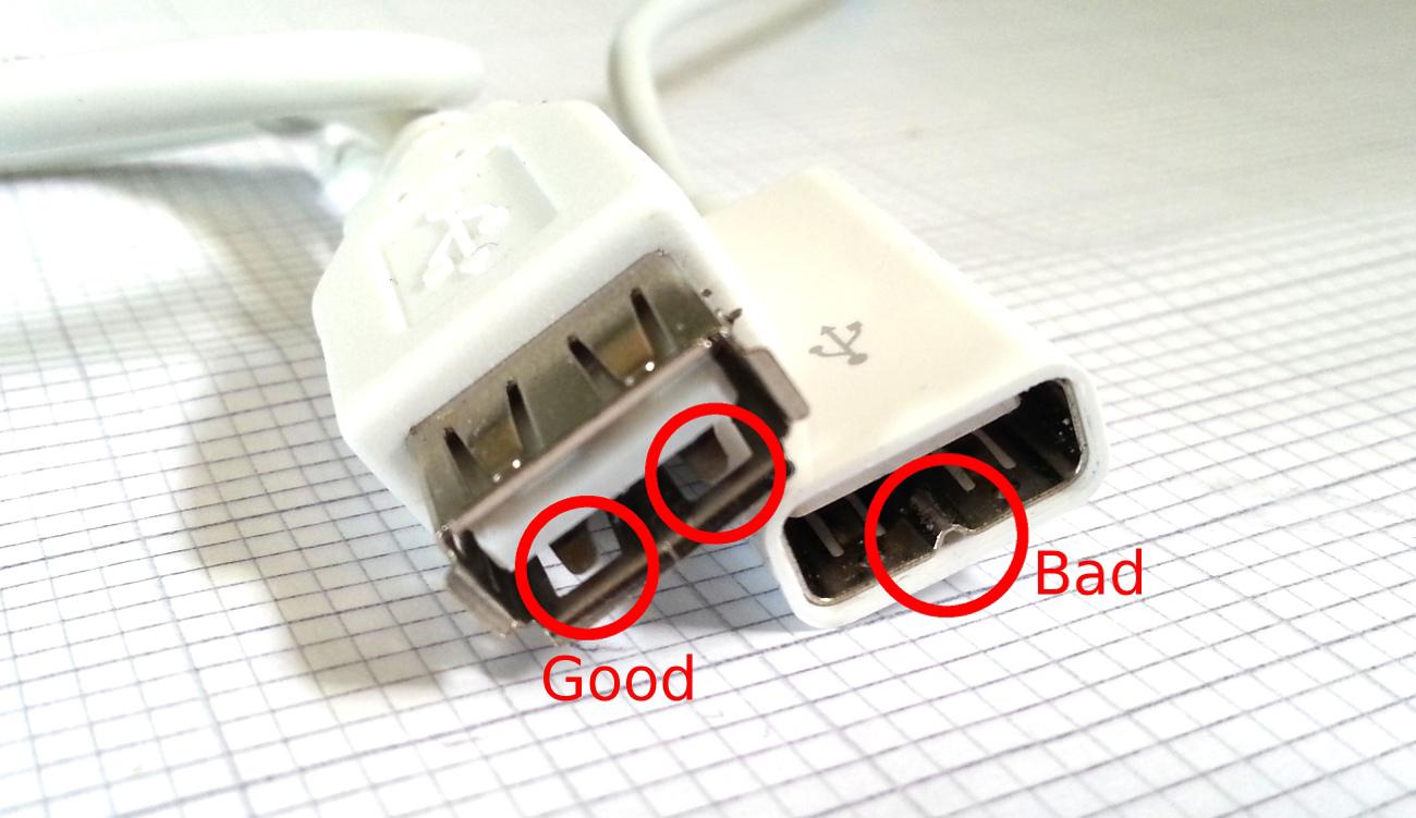
I do have one (Apple?) USB extension cable with a shitty non-standard socket that scratches away the silkscreen from the back of a Pico. See the image below:
If it's like that, it would have shorted a USB data pin to GND, which would cause your problems.
1 Attachment
-
• #7
Damn! this could be the problem. I also use the apple extension cable.
What can I do - if it is scratched? -
• #8
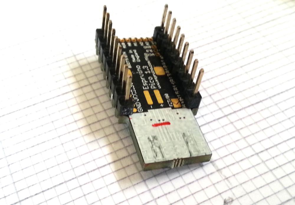
The fix is easy though. Just cut into the back of the Pico where I drew the red line, cutting through the traces that are there.
Or use another USB extension. Any sensible one will have little sprung bits of metal in it, spaced either side of the centre... and those won't gouge into the PCB and won't short out the data lines even on the board where the Apple extension went through.
I shouldn't have added a Micro USB socket outline. I wonder how many people have even used it? Maybe it's something I should just remove on the next revision... It looks like Mini USB wouldn't cause any problems, it's just having the Micro one that sucks.
1 Attachment
-
• #9
I will try this - just another extension cable - if not working, than shorten the traces.
Thank Gordon for your help and the pictures. I will report as soon as possible -
• #10
Update:
*default cable extension > not working
*cutting micro-usb lanes > not workingit seems that the board is dead :(
it has power (short red flash), but no communication (device not in USB-device list) -
• #11
I'd ohm it out to verify that no data lines are shorted to eachother or to ground/vcc... since it sounds like that was the cause of the problem. It can be incredibly hard to separate two traces, because the metal gets "smeared" along the cut.
And yeah - I don't think many people are using the micro, because those surface mount micro connectors are crap. I don't know about anyone else, but I absolutely use the mini ones because I don't like the bulky extension connectors, and the average quality of extension cables seems to be terrible despite higher prices. 4 ohm resistance along a 1 meter cable's V+ line - and 3 of the 5 I had were like that (well, the other brand was 3.x). Most mini and micro cables are usable for their intended purpose for a while at least (I have a friend who's gone through two micro-USB connectors on her phone - I just ordered her second replacement - and has gone through dozens of micro usb cables. Micro-USB was supposed to have longer operation life, but I can't reconcile that with my experience nor hers - the mini connector seems much sturdier)
-
• #13
@Jorgen wow, strange. As @DrAzzy says, can you check that the data traces aren't shorted? Also, where you did the cut should be above the area of PCB that got scraped off by the Apple connector.
The other thing to watch out for is whether the resonator (tin can) on the other end of the board has got damaged somehow. Maybe you were soldering to the 0.05" pins and accidentally shorted out to it? Without the crystal Espruino will still bravely soldier on and boot, but won't be able to get USB to work :)
On these chips, the IOs (especially USB) are pretty heavy duty. It's quite hard to blow them up so I'd have thought we could find a way to get it going again.
@DrAzzy yeah, I'll try and get it taken off the rev 1.4 then. It'd stop this happening in the future. Frustrating really - just because someone asks for it on KickStarter doesn't mean they're representative of real users :)
-
• #15
@Spocki yes I do use a external power supply (5V 1A)
I used a similar setting as shown on these picture:

- 5V connected to 5V power supply
- GND connected to 5V power supply + Pico GND (without connection GND also to Pico, everything is random and not stable)
- Data connected to Pico MOSI
- Clock connected to Pico SCK
- 5V connected to 5V power supply
-
• #17
Thanks! Hopefully you will be able to get the original working though - I can't believe it's that badly broken.
-
• #18
I take it you did check that none of the USB pins are shorted now?
 Gordon
 Jorgen

 DrAzzy
 Spocki
I have some trouble writing data to APA102 LED strip.

In my example I just do the same as the documentation said.
result is following source:
But it seems that the data I send is not the data I see.
Also if I change the pixel data to show only red pixels; there is always a kind of random colors to see :/
Hope someone can help me here to fix the problem.