Distance - Color RGBLED + Distance sensor HC-SR04 (having strange results) #2151
Replies: 35 comments
-
|
Posted at 2015-05-15 by Rek further to this, now I have set it up to only trigger on button 1 press, each time it is pressed it returns several times: Code: Results: I would expect one response per trigger, or am I missing something? |
Beta Was this translation helpful? Give feedback.
-
|
Posted at 2015-05-15 by @allObjects The code as presented does exactly one trigger... on upload, and then everytime you enter in the console sensor.trigger(). If you see it constantly doing something, you may have a grounding issue from the fact that you power Espruino from USB and your distance sensor device from you 5V power supply. Did you make a connection from GND of the device to GND of Espruino? If you do not have that, both GNDs are dancing around by the noise, and the noise constantly but irregulaerly triggers the device, 1st, and 2nd, the readings are not reliable either... ;) |
Beta Was this translation helpful? Give feedback.
-
|
Posted at 2015-05-15 by Rek Brilliant! @allObjects that fixed it, thank you very much. |
Beta Was this translation helpful? Give feedback.
-
|
Posted at 2015-05-15 by @allObjects ;) Now I know that you later plan to run your stuff disconnected from USB, just off of your 5V power supply, correct? You can do that final configuration already now and still have only 4 connections between Espruibo and the distance sensor device 'exactly' as described on the HC-SR04 page (except that you use A2 rather A1 for capturing the Echo from the device). If you have an Espruino standard board, you connect your power supply to the white Battery connecter in the corner of the standard board next to B2 pin. Make sure that (-)GND of the power supply goes to (-)GND to (-)(GND) of the battery connector, and (+)5V to the (+) of the battery connector. 'NEVER' connect the power supply 5V(+) to the Bat pin of the board, even though there are situations with such a connection that do not lead to disaster (your power supply delivers 5V and that is more than what comes from 5V USB through the blocking diode - 4.7/4.3V, but when our power supply delivers less or has another issue, USB will try to feed it and that leads to all sorts of unesirable (final fatal) results, even though there is a 1000mA fuse in the circuit). With connecting to the Battery connector you can have safely run USB connected parallel to your power supply. If ou have an Espruino Pico - and I assume that's the case - you connect your power supply's (-)GND to the Pico GND pin between to the USB tab and VBat pin - the GND pin is the first pin on the right sight looking from top and USB tab, and you connect the power supply's (+)5V to the BAT_IN pin between the USB tab and pin B15 - the BAT_IN pin is the first pin next to the TAB opposite the GND pin. Again, do not connect the power supply 5V(+) to Pico's VBAT pin beteween GND and 3.3V pin, for the same reasons as describe for the standard board, with a small difference: there is no fuse that can prevent disaster, not even for a limited time... Now, connected to and run from your power supply, you add an onInit() as described below, then you upload the code, type Disconnecting USB, pulling the power supply from the wall socket (or what ever allows you to shut it off), and then repowering with the power supply will start run your code... ;) Having added the variable to hold on to the intervalTimer returned by setInterval() allows you to stop the triggering by software: and to restart it calling Since you are an old hand, you will say that you do not like to call onInit() for restarting the triggering at all, because in your final (SW) setup you will have other things in the onInit() which should be called only exactly once... Said so, you create two functions, start() and stop() - start setting the intervall, and stop clearing the interval - and invoke start() in the onInit(). To be on the defensive side your stop looks then like this: If this is a waste of breath on you because you are already beond that, just ignore the code litany.... ;-) |
Beta Was this translation helpful? Give feedback.
-
|
Posted at 2015-05-15 by Rek @allObjects This is all very useful stuff, thanks for the detail. I am using the standard board, I am feeling my way through the world of electronics and loving how easy it is to get results (using espruino), I now have the led strip reacting to distance from the sensor. I will make sure to keep well clear of the batt connector until I am ready to go stand alone with my contraption. |
Beta Was this translation helpful? Give feedback.
-
|
Posted at 2015-05-15 by @allObjects That was quick... did not want to pull the button for stop into play yet... But may be now is the time: since you have the standard board, you may take a look at the Software Buttons - Many buttons from just one hardware button. This gives you multiple functions by just one button (BTN1), by different sequences of short an long presses, just as Morse managed to convey text over a single wire in a human (easy) to create and interprete async communication. A asynch protocol that is not as time/baoud sensitive as the async serial communication... I used the software buttons to control running lights - ok, just the three leds on the board - my first 'project' a while ago... To keep you clear from the battery connector was not at all my intention... because if you stay clear until done and connect the LEDs to VBat of Espruino, you have to reduce the intensity for the LEDs, because they will pull your USB into the ground (use values lower than 255)... 10 RGB LEDs bright white pull 600mA... already beyond 500mA what a Computer Stanard USB can deliver... (MacBook Pro complains about pulling to much from the USB, shuts the USB down... but unfortunately looses with that also the keyboard until you restart your machine - other computers may do similar things if 'friendly'). To be safe power your LEDs directly from your power supply (if they can handle the 5V)... either way - connected to battery connector or not. But again: have all GNDs tied together. Since you already have it for the sensor, you are just fine. Could you publish a short clip? ...a pic is more than 1000 words, and a clip is a multi-volume lexicon... (with that you notice I'm old fashioned... so more in the presence: ...a clip is a google result... ;)). |
Beta Was this translation helpful? Give feedback.
-
|
Posted at 2015-05-18 by Rek @allObjects I have my RGB strip powered off of 5VDC regulated which can supply up to 3amps which is plenty for this initial prototype (24 LED strip). That multiple button script will definitely come in handy. My next bit of research is going to be into getting a DMX protocol working so that I can power four emitters in a DMX chain. Does not look like there is too much out there in javascript (I saw something using node). I have a video which is being uploaded to youtube I will post it here when it has finished processing. |
Beta Was this translation helpful? Give feedback.
-
|
Posted at 2015-05-18 by Rek Excuse my shaky hands, first thing on a monday morning |
Beta Was this translation helpful? Give feedback.
-
|
Posted at 2015-05-18 by @allObjects I've no experience with DMX... I followed only some converation which made me conclude that non regular a/sync protocols need some special attention. I'm sure you already came across thesee posts. @AlexanderBrevig is very active in the audio area, and I'm sure he has some thought's about getting such things mastered... Regarding the distance sensor for light control: are youo thinking of having touch less controls instead of the classical slider things? Nice Idea... the challenge is how can you keep a value 'set', because moving away just changes the setting again... May be you are not looking for that, but: A way to control/mix in multi-dimensional manner various lights dynamically, similar to sound mixing with Turntablism? |
Beta Was this translation helpful? Give feedback.
-
|
Posted at 2015-05-18 by Rek @allObjects the aim is for an on-street interactive lighting installation for our local council, so the sensors would be strategically placed to pick up people moving through the installation and affecting the lighting around them (the lights will go back to a default routine when no one is within range). We needed some pretty powerful emitters to put through fibre optic cables and the ones available need to be controlled via DMX, otherwise the prototype I have would almost be sufficient as is. |
Beta Was this translation helpful? Give feedback.
-
|
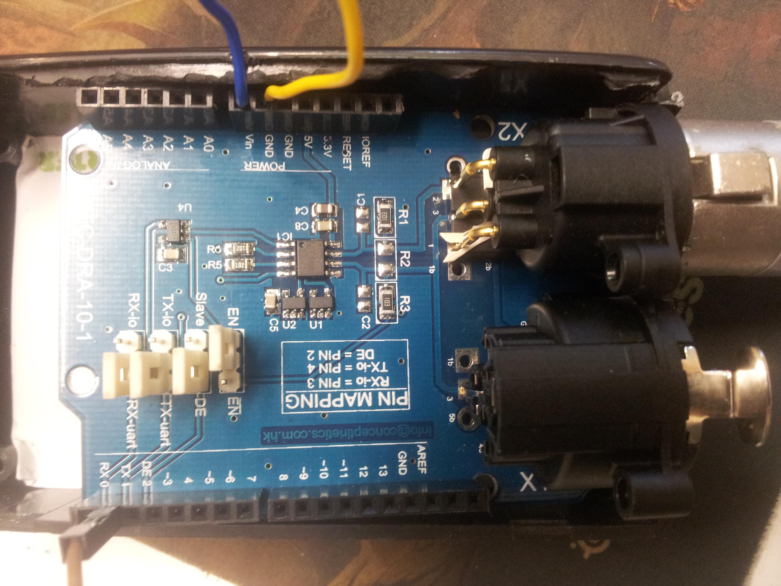
Posted at 2015-05-18 by Rek @gfwilliams would something like this work with espruino? https://www.tindie.com/products/Conceptinetics/dmx-shield-for-arduino-remote-device-management-capable/ |
Beta Was this translation helpful? Give feedback.
-
|
Posted at 2015-05-18 by @gfwilliams Yes, that shield would be fine, it's basically just a level converter to DMX levels - you just have to connect up RX and TX wires (and power/ground obviously). So are you planning on transmitting DMX rather than receiving it? If so I think it should be relatively easy to do with Espruino. |
Beta Was this translation helpful? Give feedback.
-
|
Posted at 2015-05-18 by @allObjects ...from managed inside space of managed buildings to managed outside space of managed communities. |
Beta Was this translation helpful? Give feedback.
-
|
Posted at 2015-05-19 by Rek @gfwilliams yes this is to send DMX signals, no need to receive. I was looking into the protocol, it seems to need a serial outpit and a set of data not dissimilar to what is sent to the RGB-LED's I have been playing with. I am not sure what could be used on the espruino to create a serial connection, plus the need for a three pin connector I figured a shield may be the way to go. |
Beta Was this translation helpful? Give feedback.
-
|
Posted at 2015-05-19 by @gfwilliams You can use any pin marked To send DMX, all you should need is: I think you could increase the refresh rate if you needed, and you could make life easier for yourself by not sending all 512 bytes. I haven't tried that though, so I'm not 100% sure if it'd work. |
Beta Was this translation helpful? Give feedback.
-
|
Posted at 2015-06-05 by Rek working with a greater distance, firing sensors individually, more stable output: |
Beta Was this translation helpful? Give feedback.
-
|
Posted at 2015-06-22 by Rek @gfwilliams @allObjects I was hoping to borrow some more of your knowledge. I have finally received my DMX shield, it got caught in customs it seems. I may need a push in the right direction on how to wire it up to my project. I have decided to use a pico instead now because of size in the enclosure I have (assuming it is up to the job). As far as I can see I should be able to use mostly the same pins on the pico as the full size espruino: For HC-SR04 Ultrasonic Sensor x3 Espr --- Pico Now I need to replace the Serial port which I was using for the RGB strip with USART_RX & USART_TX: PICO These need to be hooked up to the DMX shield, I assume like so: PICO --- DMX B6 --- RX 0 I then need to work out how to send the data as Uint8Array(512) instead of send4bit, I am not sure on this part. And then finally, there is the power. I have a 5v 3a power supply, I assume that this should be able to power the pico and the shield together (though I am unsure of the current pulled by the DMX shield). The shield has a 5v pin, so that should be easy, however I am not certain I can put 5v straight to the pico without blowing things up, am I save to plug 5v into the pico 3.3 pin or do I need to step it down first? Finally I can connect all of the grounds together and cross my fingers she works. Can one of you guys confirm I am on the right track, I appreciate your time. Summary:
Reference: DMX Shield: https://www.tindie.com/products/Conceptinetics/dmx-shield-for-arduino-remote-device-management-capable/ - I cant seem to find any diagrams docs on the shiend
|

Beta Was this translation helpful? Give feedback.
-
|
Posted at 2015-06-22 by DrAzzy
Ya. The STM32 series is lovely like that - they keep a pretty standard pinout for each package, and they put the peripherals in the same places - like SPI2 is always on B13-B15, etc. In contrast, Atmel (the one who makes the uC's used in arduinos) chooses pin and peripheral assignments with a monkey and a dart board.
Depends which way around it's labeled. Things that are Arduino shields are often labeled with respect to the arduino pin function, not the shield pin function. Check the Uno pinout, and connect RX to the pin that would go to the RX pin on the Uno.
Put the 5v power into BAT_IN (or VBat...), that will be regulated down to 3.3v to run the pico. Do not connect 5v to the pin labeled 3.3v. |
Beta Was this translation helpful? Give feedback.
-
|
Posted at 2015-06-22 by Rek Thank you @drazzy! I will Use the same pins on pico That just leaves: How do I send Uint8Array(512) RGB data to a specific DMX channel |
Beta Was this translation helpful? Give feedback.
-
|
Posted at 2015-06-22 by @gfwilliams Ok, so writing the data is a bit more interesting. I just tried and something like this should work: The timing isn't spot on, but I think it should be good enough for most DMX receivers. |
Beta Was this translation helpful? Give feedback.
-
|
Posted at 2015-06-22 by Rek Thanks @gfwilliams. I guess I will have to experiment to find out what sort of input the emitter expects, I have a feeling that using: is not going to yield the same results as the RGB strips, I am sure DMX will be more complicated than this? |
Beta Was this translation helpful? Give feedback.
-
|
Posted at 2015-06-22 by @gfwilliams It totally depends on the lights. My understanding is that each entry corresponds to a slider. You usually set the lights up with DIP switches so that they know what their DMX start index is I think. I guess a simple DMX RGB light would work exactly like you expect. Once you find the correct start index you'll get R, then G, then B :) |
Beta Was this translation helpful? Give feedback.
-
|
Posted at 2015-06-22 by Rek Ok, well I will do a learning experiment and let you know the results. |
Beta Was this translation helpful? Give feedback.
-
|
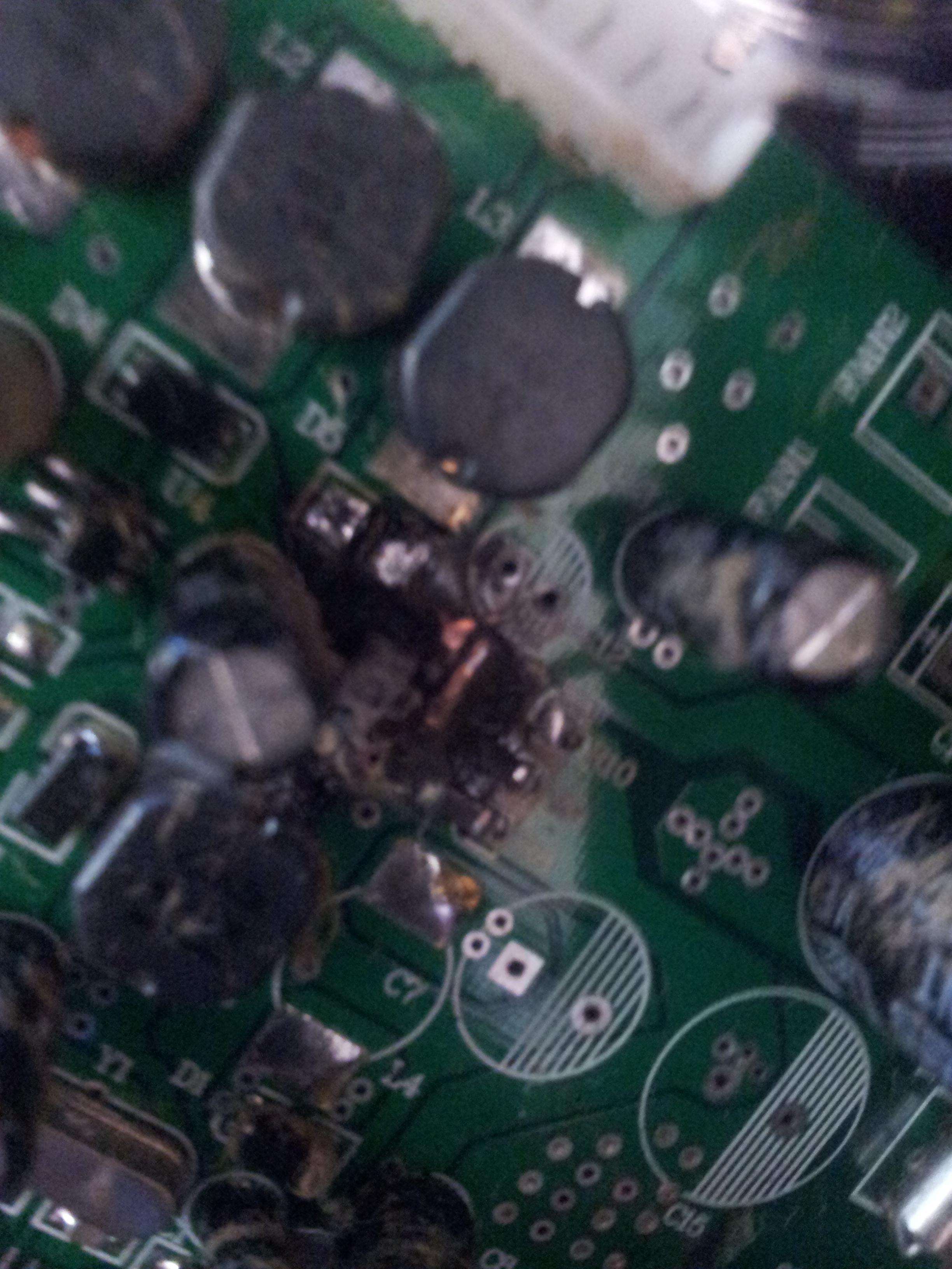
Posted at 2015-06-23 by Rek @gordon well I blew up my emitter! A capacitor exploded in the emitter while I was testing the DMX signal, it didn't simply pop its top, it blew in to pieces! I am not sure if it was a fault with the emitter or if the DMX shield sent enough current to overload the capacitor, I tested it with tx to tx first, and was not seeing any results, so I switched it over to RX on the shield, was playing around in the IDE and BOOM. When I measure the pins in the DMX shield it seems to be putting out half a volt consistently flowing from the bottom pin to each of the top pins (3 pin DMX) while plugged into RX on the shield When plugged into TX on the shield it reads .08v flowing in the other direction. I cant seem to measure any amps when I test with the multimeter in either configuration however, which seems weird to me, though I am no electronics guru. Think it was the negative voltage flow that killed it? I would be cautious to try again as these emitters are not cheap. It is a pity that DMX shield has no documentation, otherwise it would not be such a guessing game. Attachments: |
Beta Was this translation helpful? Give feedback.
-
|
Posted at 2015-06-23 by @gfwilliams By emitter, you mean the actual DMX light? Personally, I'd say that was a faulty light and you should try and get it replaced. Is it possible the light was meant for 110v systems and you were running it on 220v? Hard to tell from the picture but it looks like the capacitor is either in the power supply, or the circuitry that drives the light itself. Thing is, DMX is just a communications system - it shouldn't be supplying any power down the DMX lines - see what wikipedia says. To test it's working, you really need an oscilloscope (even if it's only a cheap hand-held one) put between pins 2 and 3. When it is outputting data you should see some signals coming out of it. You shouldn't be able to send anything down DMX that'd blow up the light though - that's just crazy. So as far as the wiring on the DMX shield goes, it'll either work or it won't depending on the wiring - although I wouldn't recommend keeping it powered up in the 'not working' state for long at all, as the Espruino and DMX shield will be fighting each other - both trying to output different voltages on the same wire. |
Beta Was this translation helpful? Give feedback.
-
|
Posted at 2015-07-09 by Rek Sorry I have been away, I am back on the project now with only a couple of weeks to get this done. I have had a hell of a time trying to solder the small pins at the end of the pico, I am sure there is a secret to it, I just have not worked it out yet. I will add to the thread soon |
Beta Was this translation helpful? Give feedback.
-
|
Posted at 2015-07-09 by DrAzzy
Solder them down to a board (ie, use them like castellated pads) and they go down easy. Might need a bit of flux, though I don't think I've used it when I put Espruino Picos onto my protoboards. ( https://www.tindie.com/products/DrAzzy/espruino-pico-protoboard-discount/ ) If you're putting pins/wires into them, it's not much harder than a normal soldering job, as long as you've got an iron with a reasonably fine point. You may have to shave the plastic around the pins down. |
Beta Was this translation helpful? Give feedback.
-
|
Posted at 2015-07-10 by @gfwilliams I guess the other solution is to use some kind of ribbon cable (which generally have a 0.05" pitch) - however stripping/soldering those is a pain too. You could also do some serious pin-bending on some 4x2 0.1" pin header, and then solder it onto the end of the board - however that'd be more of a pain to do initially. |
Beta Was this translation helpful? Give feedback.
-
|
Posted at 2015-07-10 by DrAzzy That's a good point on ribbon cable. Ribbon cable is actually not bad to strip. Put it on table, gently press razor onto it, through the insulation, but not through the copper. Flip, and do it again, then pull the insulation off the end (it should come off pretty easily now) |
Beta Was this translation helpful? Give feedback.
-
|
Posted at 2015-07-13 by @gfwilliams Nice idea - I'll have to try that. @rek - In fact, if you search eBay for 'dupont jumper' you'll get ribbon with pins or sockets on the end. If you cut that, stripped it as @drazzy says, and soldered it on the end, you could easily get 0.1" pins. ... however I'd hotglue over the end - flexing of solder joints to the thin cables can cause them to break in no time. |
Beta Was this translation helpful? Give feedback.
-
Posted at 2015-05-15 by Rek
I have started my first project, I am new to electronics but an old hand at coding.
I have 5v regulated DC power connected to my circuit (not via the espruino 5v), espruno is powered via USB, I am running code via the API
I am making a RGB LED strip change color depending on distance measured by ultrasonic echo.
I am just experimenting with the sensor module:
Now this seems to continuously send output after loaded until you trigger it via:
Does anyone know why this is?
Also, I seem to be getting very random results that don't have anything to do with putting an object in front of the sensor when I use setInterval, I have wired it up as described here http://www.espruino.com/HC-SR04
If anyone has experience with this sensor I would love some pointers.
Beta Was this translation helpful? Give feedback.
All reactions