Our New KickStarter! Espruino Pico #79
Replies: 106 comments
-
|
Posted at 2014-10-25 by @gfwilliams Thanks! @drazzy - Ahh, I didn't even realise they did AA sized lithiums that weren't 3v :) I've just updated it. I've been avoiding posting pictures of the other side because the silkscreen says 'Espruino Mini' :) I can't find a picture right now, but the attached PCB image might actually be more interesting? Basically there are no components, but there are pads for a JST connector, as well as 0.05' spaced pads for JTAG/NRST so you can use a hardware debugger on it with a bit of soldering. @DaveNI - I did look at solderless pins (I ordered some, there's a post on it somewhere), but they're actually really hard to push in. So much so that if you're not careful you could easily damage yourself/the boards. You really need a vice. I could make the holes in the board just a tad bigger so the pins fitted better, but I asked the pin manufacturers and:
It sucks really - it would have been perfect but I tried to contact 3 different manufacturers and nobody was really very interested at all.Attachments: |
Beta Was this translation helpful? Give feedback.
-
|
Posted at 2014-10-26 by @gfwilliams @sacha, thanks! @allObjects I think it'd require quite a lot I'm afraid (USB OTG support would have to be added, and that may need some other components to be done properly). Nice idea though! The ESP8266 is about the same price and should still fit on pretty easily though. |
Beta Was this translation helpful? Give feedback.
-
|
Posted at 2014-10-26 by @gfwilliams Thanks for all the support! |
Beta Was this translation helpful? Give feedback.
-
|
Posted at 2014-10-27 by @gfwilliams Thanks @drazzy - it seems some people are taking real issue with the 10 year figure, but just to show my calculations:
That's 2500mAh / 0.018mA = 138888 hours = 15.8 years So quoting 10 years leaves 5.8 for self-discharge/etc :) I was very tempted by adding ESP8266 to a kit... I may add it later - I just want to get it working first and to make sure that it's properly reliable :) |
Beta Was this translation helpful? Give feedback.
-
|
Posted at 2014-10-29 by @gfwilliams @drazzy the FET is the same FET that's used for battery switching (I think it's connected to B0 right now, but that might change). The idea is if you're plugged into USB then you can use that same FET to get a powered output. It only pulls up to VUSB, but it's still pretty handy. The pads next to the resonator can take a 32kHz crystal - I was considering pre-installing them, but they're surprisingly expensive when that size (way more than the resonator) and I'm not sure it'll be that useful - The F4 can do RC calibration against the high speed oscillator, so for most things it'll be more than accurate enough. And yes, 84Mhz. I got the impression that you can overclock it to 168Mhz (like other F4 parts) but that's not really a priority right now :) @FyberChris the 411 looks interesting - I hadn't considered it before. To be honest the 401 is still pretty good for power usage when in sleep mode. The only UFPQFN48 right now seems to be the STM32F411CE though, and that's basically 2x the price :( |
Beta Was this translation helpful? Give feedback.
-
|
Posted at 2014-10-30 by @gfwilliams
I'll have a look at that - routing is a bit tight so I'm using SMD wherever possible - but IIRC there may be some free space around there.
I think the battery is more useful than the SD card - most switchmodes in USB power packs aren't that efficient (designed for 1-2A loads) and will kill the battery life. Also when you do that you have to disconnect the device from power in order to power it from a battery - it's nice (especially with the RTC) to be able to keep it running. Also I'm not convinced there's space for a micro SD card. I may do a plug-in board with one on, but I'm not sure you can get a connector on without the micro SD interfering with the soldered-on pins. @FyberChris I've been talking to ST, and they seem pretty happy to do a deal on the F401CD for me - so that really narrows it down. Hopefully I'll announce it on the KickStarter soon. Also I have the 401 working fine, but I saw someone trying to get the 411 working with Espruino last week and he wasn't having much luck (I think support only got added via the new STM32 cube stuff). |
Beta Was this translation helpful? Give feedback.
-
|
Posted at 2014-11-01 by @gfwilliams
With sockets I think you could implement SMTP quite easily... BUT every server I've seen recently uses TLS or some kind of encryption, and that's probably not doable at the moment I'm afraid.
Yep, sounds about right :) It's going to make this really exciting. And wow, first animated gif on the forum I think. Congratulations! |
Beta Was this translation helpful? Give feedback.
-
|
Posted at 2014-11-08 by @gfwilliams Yes, it's ok, although not perfect because the board is extra thick. Having the edge does mean that adaptor boards could just be soldered right on the end. I'm wondering now whether to have one full hole and then a half hole on the end. It depends how easily that can be done by the pcb manufacturer. |
Beta Was this translation helpful? Give feedback.
-
|
Posted at 2014-11-14 by @gfwilliams There are already pads for a JST battery connector on the Espruino Pico, if that's what you meant? I'd considered the break-off bit, but as the board will be 2mm thick I kind of think the force needed to snap the end off might risk damaging something on the board. |
Beta Was this translation helpful? Give feedback.
-
|
Posted at 2014-11-19 by @gfwilliams @user7114 It should be very easy - I'll be adding the ability to use the filesystem API on any pins, so you should be able to just connect an SD connector on wherever you want. @asez73 Thanks! Yes, yesterday was pretty awesome :) |
Beta Was this translation helpful? Give feedback.
-
|
Posted at 2014-11-20 by @gfwilliams Thanks! At least a year ago, KickStarter seemed to have a bit more traffic to it than Indiegogo. It's maybe not so good this time around though - I did notice that things on Indiegogo seems to pull in a bit more funding... Personally I also think that KickStarter vets projects a bit more thoroughly than Indiegogo. I see some stuff on Indiegogo that's so obviously a fraud (or just a copy of something else). I think being on KickStarter makes it seem a bit more legitimate :) |
Beta Was this translation helpful? Give feedback.
-
|
Posted at 2014-11-21 by @gfwilliams Thanks - it's a good idea... I'll have a think about it, but initially it looks a bit tricky trying to get it in without making the board longer. I do like the idea of having extra 'shield' boards though. Problem is, people do hate change. Every time I say I'm changing something (even when it's good) someone complains :) |
Beta Was this translation helpful? Give feedback.
-
|
Posted at 2014-11-22 by @gfwilliams Thanks! £64.5k now with 13 hours left! I have no idea what people will order after the KickStarter, but there's a small possibility that with those orders we might even hit the £75k stretch goal! The crystal through-holes are on my list - I'm not 100% sure, but if I can get a bigger 32k crystal in there the price of it may drop enough that I can fit them to all boards and you won't need the holes. Male 1.27 on plugin boards would be ideal, because then you get the option of soldering them straight on - saving a bit of money and potentially meaning that you can fit the boards a bit closer together. I'll try and get extra peripherals on the board, but apart from I2C it's not vital. I will probably add software USART soon (we already have SPI) so while it's not ideal, you'd be able to use whatever pins you wanted. |
Beta Was this translation helpful? Give feedback.
-
|
Posted at 2014-12-11 by @gfwilliams There's actually Micro and Mini USB now. I thought if I was going to have to cover up the pads then I might as well put on everything I could. An SMD-able board had been suggested - but it's a long way off I'm afraid. Long term I'd like to make one SMD board that I could produce in volume and then fit to any other board that I sell. But as @drazzy says, it should be trivial to take the designs when they're released, and then to remove the pins and put something else on. Having said that, the Pico should be pretty good for small scale commercial use. That was the idea. I'll try and produce an eagle library for it, so it should be trivial to make a board that it will connect to. Personally I think that for small-scale manufacture, through-hole is probably still the way to go. If you've got a reflow oven, solder mask, and a good PCB then you might as well just make your own PCB with an STM32 on it. |
Beta Was this translation helpful? Give feedback.
-
|
Posted at 2014-12-12 by @gfwilliams @d0773d what if the Espruino Pico board had castellations around the edge in addition to pins? I'm not convinced it'd be a good idea to have them for USB because of the risk of shorts, but nothing stops you from cutting away the edge of the PCB you connect it to so you can still get a USB connector onto it - or even just blobbing up the solder if its for personal use. |
Beta Was this translation helpful? Give feedback.
-
|
Posted at 2014-12-31 by @gfwilliams It's good thanks. I'm taking a break for the next few days, but the parts that had a longer lead time are now ordered, and there's now hopefully a final board design, with fabricated PCBs waiting for me at home for when I get back. So when I'm back I'll build up some boards and test them out, and once I'm happy with them I'll get the rest of the stuff ordered - and manufacturing could start around 3 weeks after that. And yes, the castellations added 10p, so I'm going to go for it unless the board manufacturer absolutely can't handle it (they didn't like the fact that they go around 3 sides of the board, but I think we can workaround that). |
Beta Was this translation helpful? Give feedback.
-
|
Posted at 2015-01-07 by @gfwilliams Thanks - that is pretty small! Are those 0.1" pads, or 0.05"? If you imagine those long gold pads, but a bit shorter and with a hole in the middle then that is what the Pico's will look like. It'll mean you can easily solder 0.1" pins to it, or you can place it on a PCB. |
Beta Was this translation helpful? Give feedback.
-
|
Posted at 2015-01-08 by @gfwilliams Yes, the 3 internal pins are GND/3.3v/VCC - they are already on the 0.1" pin strip so are already on castellated pins. The only reason they exist is if someone wanted to make a shield. Good point about the overlap of pins. It seems insane that you can't stack two sets of 0.05" next to each other. I'll have a think about what can be done, but as @allObjects says the routing is very difficult (I've just had a quick look at it again). The connector only just fits in as it is. Personally though I think most people will use 0.01" pins, or 'shims' that solder on using the board's castellations. If you're soldering a tiny daughter board onto just the 0.05" pins then you're probably able to snip a tiny bit off time side of pin strip with a pair of pliers. |
Beta Was this translation helpful? Give feedback.
-
|
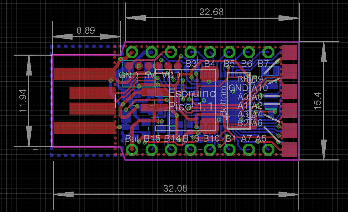
Posted at 2015-01-16 by @gfwilliams I'm afraid I doubt those will work. For #1 there's no way to get two tracks in there side by side, and for #2 you can't get A4 out inbetween the ground pad and A4's pad. I have given this a pretty good go - it took me a very long time even to get that many pads in there. I guess the other (more simple) option is just to swap the position of GND and VDD, such that VDD was the one nearest the end of the board. That would mean that for any device with its own regulator you had no need to fit the pin at the end (see picture for what it's like at the moment). Attachments: |

Beta Was this translation helpful? Give feedback.
-
|
Posted at 2015-01-16 by @gfwilliams One other thing I could do is swap as follows:
So then you had GND available right on the end - might be preferable, but it then means that A4 won't be available by the castellations. |
Beta Was this translation helpful? Give feedback.
-
|
Posted at 2015-01-16 by @gfwilliams Any thoughts on this as a different layout? I didn't really want to change the board much after my last set of protos, but I guess this might be worth it. It's pretty much a given that someone, somewhere will complain about A4 though. It'd be good to get this sorted soon - ideally I would have sent it to Jaltek yesterday, but I'm still waiting to hear back from Abracon about the suggested load capacitance to use for their 32k crystal. Just did a test and the board really does manage power draw down to 42uA in standby though. Espruino doesn't hit that quite yet (I have to figure out what needs turning off first!) but over time it'll get there.Attachments: |

Beta Was this translation helpful? Give feedback.
-
|
Posted at 2015-01-16 by @gfwilliams I don't really get what you're suggesting... That big blue rectangle is the ground pad under the STM32 - you can't put a gap in it so you can put A4 through it like you've drawn it. |
Beta Was this translation helpful? Give feedback.
-
|
Posted at 2015-01-16 by @gfwilliams The bottom of the chip is bare metal, so if I put a via on the inside of those pads I'm basically relying on the solder resist to stop a short - not a good idea at all. Also (at least when I'm hand soldering) that pad is absolutely vital for the correct soldering of the IC. The solder on it melts, and 'sucks' the IC into the correct position so that everything lines up. If I changed its shape it might alter the way the chip sits. |
Beta Was this translation helpful? Give feedback.
-
|
Posted at 2015-01-16 by @gfwilliams Anyone else? Do you think the new pin configuration is better that the old one, that would have required trimming down one of the 0.05" pin strips? |
Beta Was this translation helpful? Give feedback.
-
|
Posted at 2015-01-17 by @gfwilliams I'll look at @allObjects idea next week, although I'll need to be careful. There is a ground plane right under the high speed oscillator to cut down on interference, so I don't want to move that too much. However as @frida suggests we're really close to the point where the boards are ready to be made. The old L arrangement is really not a huge problem. It's extremely unlikely that anyone will use it, especially as there are now castellations so most people will just use them. On top of that I have prototypes of the old design that are tested and that work, and there's no way I have time to prototype the new one, meaning I'll have to make 4000 UNTESTED boards in order to save 2 people from filling down a connector a little bit. If it delays everyone else getting their board, I doubt they'll appreciate the extra 0.05" gap. Honestly the more I think about it I'm not convinced it's a good idea at all. In the interests of getting everyone their boards on time I think we should probably just drop this and go back to the original L design. |
Beta Was this translation helpful? Give feedback.
-
|
Posted at 2015-01-22 by @gfwilliams Yes, I will be. I'll do it after the PCB has been okayed by the manufacturer (in case they need any changes made so they can tile it properly) - but hopefully that'll happen in the next week or so. |
Beta Was this translation helpful? Give feedback.
-
|
Posted at 2015-01-27 by @gfwilliams Hi Lawrence, Yes, The Pico appears as a USB Serial port - usually For example, to turn the LED on from the shell, just write: But you can actually program in more advanced behaviour. If you want to 'shift' data out in some format, just write a JavaScript function to do it and send it over the same way. You can then just call that function when you want to do things: There's some more info on sending commands from another computer here: http://www.espruino.com/Interfacing You could write your own protocol too - by moving the console away from USB (using But personally I'd just use JS as it's actually pretty efficient, and easy to understand/debug. |
Beta Was this translation helpful? Give feedback.
-
|
Posted at 2015-01-27 by @gfwilliams Ahh, great - I've had a play at using node red to control an Espruino, and it works really nicely with the serial module. The new versions (in GitHub, not sure if they're released yet) allow submodules, so you can do everything you need in node red. Having said that, if you wanted to actually make a module it'd be amazing. Getting data back from Espruino via Node Red nodes is a bit of a faff at the moment (if you send data down the serial port then it's hard to make sure that the value that's returned goes to the right input node). I think there are one or two people using Espruino that way - especially because you get Analog IO, but not that many. I think a lot of people haven't realised that it really is that easy. It's mostly my mistake for not saying much about it, but I'm hoping that the Pico (that's more plug-sized) will get people's attention a bit more as an IO board. |
Beta Was this translation helpful? Give feedback.
-
|
Posted at 2015-02-10 by @gfwilliams Hi Bert, Yes, sorry - I've been a bit busy lately trying to get the kits together! Yes, it was finalised last week - lets just hope the PCBs are good when they arrive :) I'll try and get the part outlines online this afternoon - i'll post up on the other thread. I'd actually really appreciate some help with the adaptors, so maybe we can have an area on GitHub? I think it would be painful trying to work together on one Eagle schematic, but I could probably script something up that will merge a whole load of different gerbers into one big gerber full of different adaptors that we could get printed. |
Beta Was this translation helpful? Give feedback.
-
|
Posted at 2015-05-14 by @gfwilliams Yes, that looks interesting. Nice to be able to just stick a Pico in the side and then use it for measurement + control! |
Beta Was this translation helpful? Give feedback.
-
Posted at 2014-10-24 by @gfwilliams
It's just launched, and it's awesome!
https://www.kickstarter.com/projects/gfw/espruino-pico-javascript-on-a-usb-stick
Please think about supporting me - the one's really cool, and I'd love to see it succeed!
Beta Was this translation helpful? Give feedback.
All reactions