-
• #2
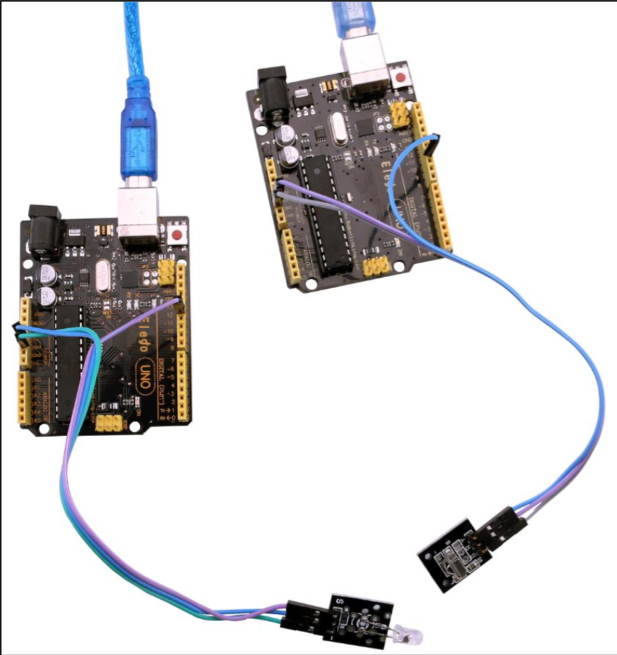
Hi, typically you'd have a ground, power and a data pin on a module like that. It's the data pin you will send on. I'd guess pin 2 in your pic - making the unnumbered pin, power. For espruino it would be 3.3v power, arduino is 5v. Maybe confirm it is good at 3.3v, I would imagine it is but do not know.
-
• #3
Would I be right in assuming the analogWrite should be effecting the power pin on the module I pictured?
// Start the 38kHz square wave analogWrite(A5,0.9,{freq:38000}); // Send the pulses digitalPulse(A6, 1, times); // Wait until pulsing is finished -
• #4
Hi no, your pulsing signal is your data which should be sent on the data pin. So wire power to 3.3v.
-
• #5
@Ollie I'm pretty sure that's not right... @wardy's doing the right thing and you need to connect the two pins of the IR transmitter to A5/A6.
@wardy what you were doing is fine (A6 should be 'OUTPUT', A5 should be 'GND'.). There doesn't seem to be anything on that circuit board apart from the LED - all it's doing is bringing the LED pins out to some slightly more sturdy pins. Despite the fact that the diagram says GND, it's fine to connect it to A5.
Just a bit of background: To make the signal easier to receive, IR remote controls don't just pulse an IR LED once for each bit of data, they turn it on and off repeatedly at 38kHz (which can then be picked out from ambient light by the receiver).
To do that easier on Espruino, we use a hardware timer (analogWrite) to pulse one pin at 38kHz, and then we output the actual signal on the other pin with digitalPulse. It works because the LED is a diode - it'll only output light when the voltage on it is one way around, and there's no harm to it when the voltage is reversed.
If it was something more complicated than a simple LED then things would be harder though, since you probably would would to avoid reversing the voltage across it.
-
• #8
@Ollie not to worry! I hadn't had a chance to try again since my post. Although I have gone out and bought a normal IR LED since to try out incase I still have problems. So i'll have a try again tonight and post back how it goes.
@Gordon Thanks for the clarification. So I take it that IR LED is constantly shining the 38kHz frequency and the digitalPulse through the other pin is interrupting that at the scheduled times in order to actually transmit the signal?
If that's the case I was reading that diodes
In electronics, a diode is a two-terminal electronic component that conducts primarily in one direction;
Does that not mean the the 38kHz turning on and off is very weak?
Here are some other pictures from the documentation for the module incase you are interested. One shows it wired to output, ground and power of an Arduino :$
1 Attachment
-
• #9
I think what they're doing with the kit is making it so that every module has 3 wires, in the same places. The idea is that you can just do the same thing and then replace the module without worrying about re-wiring.
For the LED, think of it like this:
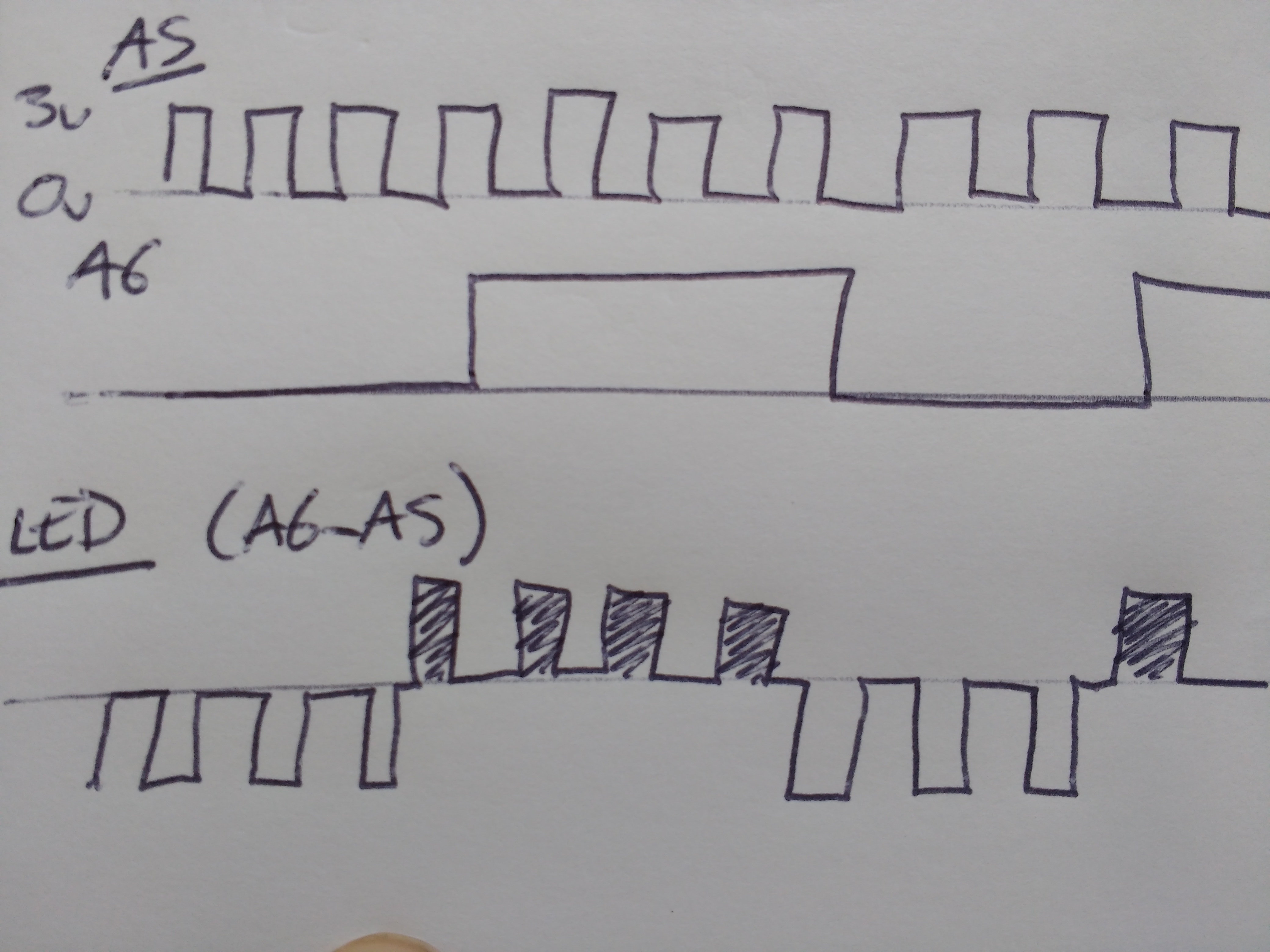
- A5 has got a 38kHz square wave on it, between 0 and 3.3v
- A6 turns on only when you want the light to come out of the LED
- The LED is connected between A5 and A6, so the voltage across it is
A6-A5. - The LED itself will only conduct (and light up) when there's a positive voltage across it. A negative voltage won't hurt, but it won't make it light up.
So if you look at the graphs below (time is left->right, voltage is up->down), at the bottom there's
A6-A5. When A6 is 0, the voltage goes between 0 and -3.3v (so no light), but when A6 is 3.3v, the voltage is now between 0 and 3.3v, so when the square wave goes high, the LED lights up (shown by the shaded part of the square wave).(So the signal out of it isn't really weaker, it's just only on half the time)
Does that help?
1 Attachment
- A5 has got a 38kHz square wave on it, between 0 and 3.3v
-
• #10
Yes that's great help thanks! My only question now is about how the square wave on A5 can be between 0 and -3.3V when A6 is 0. Is this a good answer http://electronics.stackexchange.com/questions/10322/what-is-negative-voltage ?
-
• #11
Yes, that sounds like a good explanation...
Not sure if it helps, but if you unplugged the IR LED and put it in the other way around, now it'd have 0 to 3.3v on it and would be turning on, and when A6 was 1, it'd have 0 to -3.3v and would turn off.
 Ollie
Ollie wardy
wardy Gordon

Hi I've been trying to follow along with http://www.espruino.com/Pico+Infrared but I am having trouble with emitting IR from the LED. I purchased a starter pack intended for an UNO and the IR led is attached to the PCB. I've been trying to figure out how it should be connected to the Espruino because one of the pins is a ground I'm not sure that it can be written to with analog write ?
Any help would be greatly appreciated, really enjoying Espruino so far :D
p.s. using a full size espruino
1 Attachment