-
• #2
Can you post a pic of the 'inners' of the broken car, focusing on the wires going to the solenoids?
-
• #3
Another question is: was the control digital or proportional?
Digital means that it did not matter how much the control joy stick or wheel was turned, the steering is either max left, straight, or max right. If no solenoid is powerered, a (soft) spring centers the steering rod for going straight.
This technique has a permanent magnet on the steering rod that is pulled by one solenoid at the time. The control is either 2 buttons or a stick or a wheel that switch on the left or right channel of the 4 channel remote control. The other 2 channels are used for forward and backward - usually over a full H bridge.
Proportional means that the steering is proportional to the tilt or turn of the control element.
Using PWM (analog write) is actually a cool thing to overcome the digital steering: the on cycle is not enough to pull the steering rod all the way... ;-)
Since you have a brain (versus no brain form before) in the car, you can operate the opposite solenoid as well (with reverse current flow) to get a better control... (assuming there is a permanent magnet on the steering rod vs. just a plain piece of iron metal). Pull and push at the same time is just draining your batter a bit more and you need full H bridges for the solenoids as well.
-
• #4
Hi @allObjects, definitely digital - it's all or nothing on the steering side that works. Here is a pic.
The two wires not connected to the orange wires were originally connected to where my finger points. If I wire them to the board, and put 3.3v from Espruino across each of two points one of the solenoids works - the other does not. I can reverse the voltage on the same connections and get a push effect, but i don't think this is how it was designed to work otherwise the other connection would be redundant. If I just apply voltage to the wires, when they are not attached to the board, then neither solenoid works - so the board is providing something in addition that I do not understand.
1 Attachment
-
• #5
I know exactly what you are dealing with... the IC is the famous TX-2B / RX-2B or TX-2C / RX-2C chip set... - google
4 or 5 channel remote control IC 27MHz(images and then sites) where you find plenty of information... including some details of the drivers for the motor and solenoids, for example, this with variations.As I see from your pic, there is a plenty of transistors/fets on the board that drive the things... you can reverse engineer, but you also can go just by yourself. What I suggest is to get a quad half-bridge chip, where with one you drive the motor, and with the other you drive the solenoids in series, for example something like SN754410 Quadruple Half-H Driver running on 5V, but able to run on 3.7V: Allegor A3988 quad half bridge drivers.
Since you do not have a lot of space, you may salvage the drivers from your current board - if they are still any good. Otherwise, check out some examples for H-Bridges with bipolars or examples for H-Bridges with FETs. You may find either on your current board...
-
• #6
Thanks! Will check this info and links out and report back
-
• #7
...here my version(s - had two of those to do indoor - on table - races while living in a crammed place in a very cold region...).
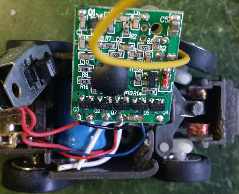
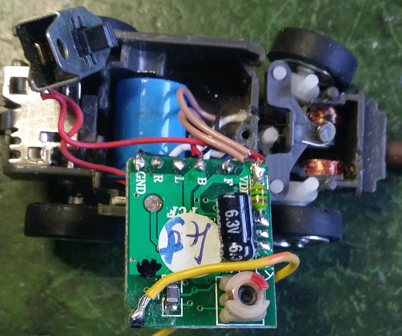
On the back of the board you see F(orward)-B(ackward) with motor connections (red and black wires), R(ight) and L(eft) with connection to one side of the solenoids (white wires - disconnected) and VCC (brown wires).
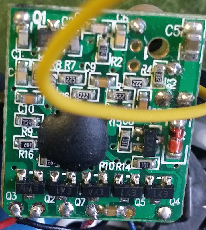
The solenoids are driven with NPN 'open-collector' - assuming it is just - transistors: VCC-Load[=solenoid]-Collector/Emitter-GND... and if NMOS FETs switching the low side, there fore, more precisely: VCC-Load[=solenoid]-Drain/Source-GND (Q3 and Q2) - driven over ~1K Ohms (102 --- 10 x 10^2).
Q4 and Q5 - same as for solenoids control (EY1) - together with Q6 and Q7 - some PNP transistor (or PMOS FETs; IYA - IY^ ?)- build the H-Bridge for the motor control - hight side driven over ~100 Ohms (101 --- 10 x 10^1) from opposite driver, and low side driven over ...cannot see it.
The solenoids have a resistance of about 20 Ohms each. Between them is the cylindric neodine magnet moving the steering rod to the left and right, and over it is the pivot of the spring with two legs centering it to and via the trim post (white plastic with the flat side). A very simple but very smart way to have it all: control and trim (for going straight when no solenoid active).
There is nothing additional to the steering but the alternate powering of the solenoids. Try to measure the resistance of yours... If it broke of, the wire is lacquered and therefore you did not get a pass through.
Power is a single 1.2V 80mA NiCd(?) cell. What you cannot easily see on the backside - under the 100uF 6.3V electrolytic capacitor - there is a (3+1) four-legged SMD IC(?) which I assume makes a voltage booster with the L3 and glass diode D1 on the front side. IC reads DF N6 - guess just the package ID :(... and just another transistor with cheap booster switch for HF and control side only...
The boards are from about 2004. The switch is my addition... to have the car ready charged for a quick race. The constant on drained the battery pretty quickly, even when car not driven.
References: datasheet datasheets2 datasheet3.
3 Attachments
-
• #8
Neat - so the solenoids are connected together and need a push-pull drive?
I guess the easiest solution would be to use a 4 channel H bridge controller. You can get several types on eBay or an L293 chip could work well. That would allow you to control the motor and the steering.
Another option is to cut the controller board in half and try and use that, but presumably one of the transistors has blown if it will only steer in one direction.
-
• #9
Thanks guys. I actually found the transmitter and receiver board on ebay and ordered a pair.
After reading some of the above material, I thought it might be simpler to cheat and control the RC transmitter itself from Espruino leaving the car to handle the signals.
Though tonight I wonder if the non working solenoid is damaged as I can't wire that to the good connections of the one that works, I would have thought that would work?
Anyway, I'll come back to this thread when the fresh circuit board arrives.
-
• #10
RC car now has a micro servo installed in place of the solenoid system. Untested but I think should have steering and forwards.
re the motor and reversing polarity - after googling I see a switch circuit which includes a double pole switch can do this? Could Espruino play the part of the switch?
1 Attachment
-
• #11
Ic, quite interesting...
Could Espruino play the part of the switch?
Certainly can... are you saying: placing an Espruino on the car? ...and where the power plant for the Wifi?.... I hope you have Puck(s) waiting for you... the perfect low power thing (B)LE! --- Until then, a Pico with an ESP8266 could do... or just a ESP8266, may be... (an ESP8266 ESP-01 onto which EX chip you solder some more wires. The issue of the power still remains as well as how you want to control the motor.
I'd start with a Pico and a ESP8266 and a full H-Bridge. The Pico is string enough to run the servo directly from its pins. The motor you run over the half bridge. I you can salvage the driver - H-Bridge - from the previous board, you are ready to go...
What's your plan?
-
• #12
Plan?
In all honesty there's not much of one. I was pretty certain one of the coils on the solenoid was damaged, so needed an alternative. I thought this servo might just fit.
Really what I envisioned when I started was 3.7v battery powering an ESP8266 which listens for MQTT control messages. The motor and the servo powered from the ESP8266. If I could use analogWrite for motor then I'd have speed control, but that wasn't essential, though it seems I'll have get into analog anyway now the servo is included and I've no idea if ESP8266 is up to this - voices at back of head keep saying timing and WDT and capacitor.
I have an Espruino Wifi I could use but that's not a throwaway strap it to a broken RC car, item.
My question re Espruino being the switch was basically can I create the circuit that flips the polarity to the motor without the h bridge since a double pole switch can do it, can I not setpins via Espruino to emulate what the switch adds to that circuit.
I'm probably being very naive - I don't get enough time to play with this stuff, and I've very little knowledge about electronics beyond household.
-
• #13
You can do that, but I do not know how much current the motor needs and also whether the pins can handle the 'spikes'.... since it is an inductive load. You can sacrifice 4 or 6 pins in two groups. One group you set to Hihg, and the other one to LOW, and vice versa for the opposite direction.
-
• #14
Thanks @allObjects, yes the current is a concern, given that the ESP8266 needs a capacitor for reliable wifi that had crossed my mind also.
Re the pins set up, conceptually that sounds like exactly what I inferred/guessed/hoped might be possible, i imagine I would need to be switching pinMode in my code?
-
• #15
...you put your (Espruino) pins in an array and output an array of all lows for stop, 3 highs and 3 lows for one direction, and 3 lows and 3 highs for the other direction... see digitalWrite() reference.
-
• #16
Thanks again @allObjects
-
• #17
I must apologise too - for some reason I've had a mental block re this. It is very simple now you've pointed me at digitalWrite and the high/lo capability of that - and I feel a bit foolish. Re the reference to 4 or 6 pins in groups of 2 or 3 - you're suggesting using those to give me enough current for the motor, effectively parallel connections?
-
• #18
Yes, see this GPS powered by Espruino pin(s) conversation.
-
• #19
Nice tutorial!
Needless to say 3 pin pairs not enough - nothing from the motor. Wiring connected right since 2 leds worked fine. I've researched and the ESP8266 has only 12mA per pin and as best as I can tell (from trying to find the part on the web) is the motor needs 70mA at 4.5v. I'm inferring more at 3.3v based on P= V * I, or perhaps it will just run slower.
The good news is the micro servo works great. The linkage is tight enough, and the steering makes both of its stops. The servo module makes it a breeze to work with and the code is lightweight enough to fit in to my program which listens over MQTT and go in the ESP8266.
So next steps. Wait for the new control board to arrive which will have the H gate on and try piggy back that, so motor driven from the lipo battery. Or, failing that try find a smaller motor, maybe the type that goes in micro drone and try fudge that in, accepting that car will be slower if it can be made to work at all.
I can do neither currently so, I'll come back to this thread when I can.
-
• #20
Thanks for the compliment...
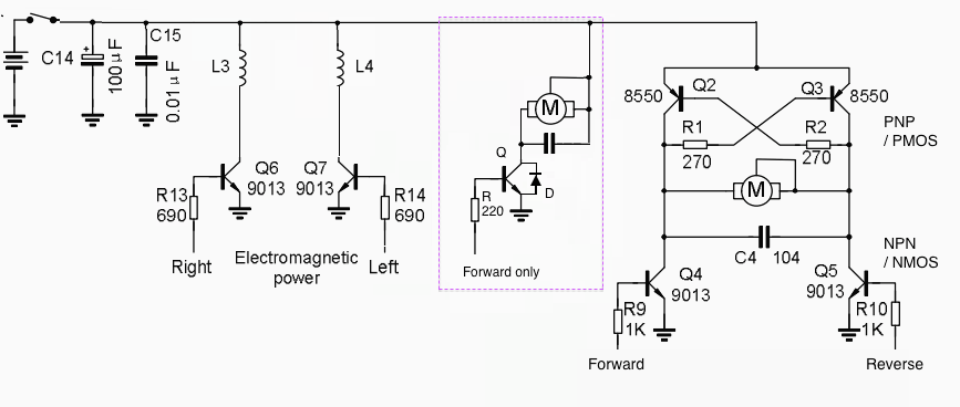
Simply get yourself 4 bipolar/mos fet transistors - 2 pnp/p channel and 2 npn/n channel - and 4 resistors and cobble together an H bridge like below to the right. If you want to get it temporary going for some testing and SW development, put something together like in the middle (in dashed box). Almost any NPN transistor Q can do that can handle 100 mA Collector current (to be accurate, you would have to measure the stall current: hold the motor drive shaft and apply power and measure the current, that's the max the motor can draw). The diode D is for protecting the the transistor from reverse voltage generated by the motor. The resistor R I thumb-calculated for 3.3V 14mA... (more precise: 180 Ohm). An Espruino pin can source or sink 25mA, but with the caveat of voltage at the pin significantly lower than 3.3V or higher than 0V. Depending of hFE - amplification factor - of the transistor you should get enough power with a few mA driving the Basis. Play with the resistor and hFE of transistor you have...
1 Attachment
-
• #21
I think I'd like to give making that circuit a shot - thanks. And I do appreciate the time you've put in to helping me on this. I will report back soon.
-
• #22
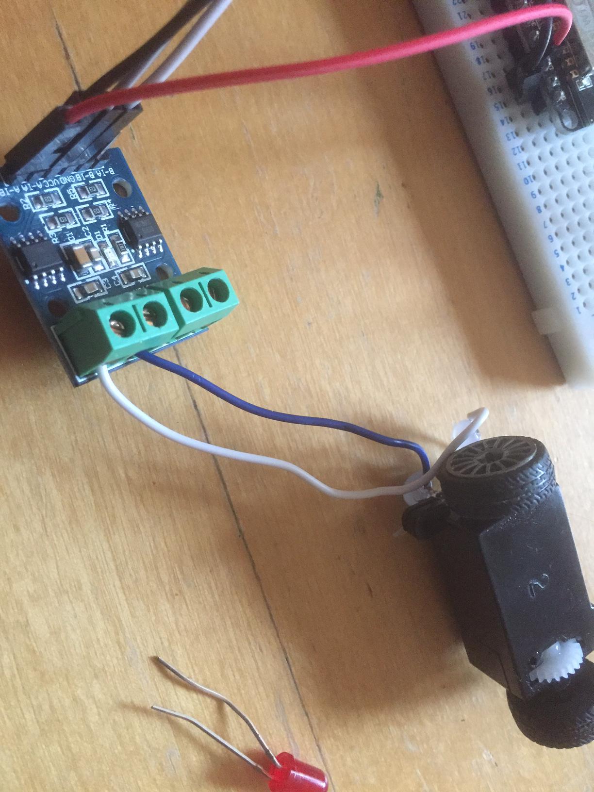
Some progress. I didn't build the H Bridge circuit. I went to Maplin asked about the bits needed and was met with glazed eyes - more glazed than mine! So I found this on ebay (see pic).
I have it wired and the best thing is it supports analog - so this micro RC car which had digital steering and drive now as analog running both.
My next challenge is to try run the lot on a 3.7v lipo attached the nodeMCU Vin - which "should" be for 5 volts. I've wired it and all the lights come on, but whether there's enough to run wifi and the H bridge plus motor I've no idea. Anyone?
If that works I'll refine the sketch and report back again.
Edit: Needless to say there is no way the body is going to go back on this car now.
1 Attachment
-
• #23
So far I have the steering turning and motor running over Telnet - this is a good sign although I'm guessing the MQTT messaging might be a bit more power hungry.
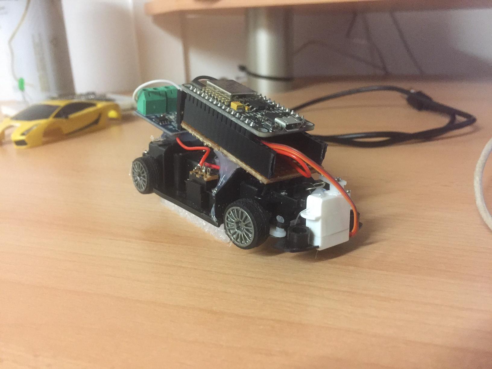
And this the car. I've tried to make it look like a car - but it's not the lamborghini it once was :)
1 Attachment
-
• #24
...now it's a Lambespruino! ...sounds still designer Italian!
Thanks for sharing!
-
• #25
Nice - that's still pretty compact! I'm not sure if MQTT really would increase the power requirements much. Surely you actually want it serving up a webpage with control via Websockets? :)
If you wanted to add a super hacky camera to it, you could look at: http://www.espruino.com/ADNS5050
This is the kind of thing that you could design a custom PCB for pretty easily (Just the ESP12 and motor driver) - with it you might even be able to fit the top back on the car :)
 allObjects
 Ollie
Ollie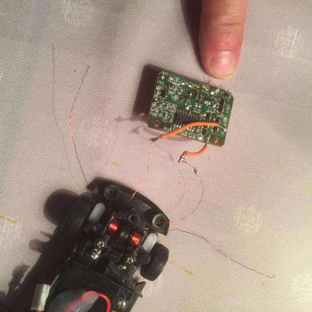
 Gordon
I've a broken RC car I'm trying to make driveable over the web using MQTT messages (for my kids). I'm nearly there, but the cars steering looks like it is two solenoids. The board that provided this does not work properly, so it only steers one way. Can anyone help me build something that will operate the solenoids.
The car was a 3v (2 * AAA) and I've replaced this with a 3.7v 500mA lipo battery. Eventually I'd like a throwaway ESP8226-12 to be the brains of it. I have a working testbed that listens for MQTT messages and sets LEDS using a combination of digitalWrite and analogWrite. It's just the solenoids I can't figure. It is not enough to just put 3.3v through them, the board must have provided something in addition to this? I can't find much of help on the internet